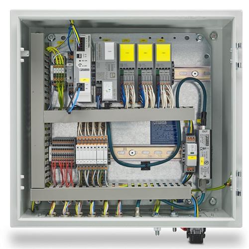
Justification for application of IEC TR 60890 method for temperature rise calculation for medium voltage controlgears and switchgears
0 Introduction
-
The use of IEC TR 60890 to replace temperature calculations with temperature tests, has never been and will never be recommended by ConformEx, in general and for all ATEX certification projects for controlgears and switchgears and maybe applied for rare and special cases;
-
ConformEx firmly believe that no calculation method can replace temperature testing, especially when an accredited Laboratory is available and there is no justification not to perform the test.
1 Purpose
For the purpose of ATEX certification for low voltage control gears and switch gears, performing temperature measurement type tests required by EN IEC 60079-0 is necessary and in some cases, calculation method according to IEC TR 60890, which is exclusively related to low voltage control gears and switch gears, could be replaced testing operation by the explosion-proof lab.
This article includes a guide for evaluation the possibility to apply the method described by IEC TR 60890, also for medium voltage control gears and switch gears.
This article provides a technical justification for applying the temperature rise calculation and verification methodology described in IEC TR 60890:2022, originally developed for low-voltage (LV) switchgear, to medium voltage (MV) terminal boxes.
2 Rationale for Using IEC TR 60890:2022 Method for MV Terminal Boxes
2.1 The sameness of fundamental physical principles
The method described in IEC TR 60890:2022 is based on network modeling of thermal resistance and electrical power losses (I²R).
These principles apply universally regardless of voltage level:
-
Electrical losses in conductors and connections cause heat generation;
-
Heat dissipation depends on thermal resistance of material and enclosure design.
The calculation of temperature rise by power loss and thermal resistance is therefore applicable to MV terminal boxes.
2.2 Simple and similar construction and thermal behavior
MV boxes have a simple structure, consisting mainly of conductors and connections, and do not contain complex equipment with complex thermal behavior at high voltages.
The methodology for calculating conductor and connector losses, and modeling thermal pathways, remains valid.
3 Justification of condition and assumption of IEC TR 6089:2022
The following table examines the verification conditions and assumptions for correct calculations in the IEC TR 60890 standard for MV boxes.
clause of standard |
description of requirement |
description of evaluation |
evaluation result(accept / reject) |
4 |
verification condition |
||
the assembly is designed for AC currents and frequencies up to and including 1600 A, 60 Hz. |
|||
the assembly is designed for DC currents up to and including 3200 A |
|||
conductors carrying currents in excess of 200A AC, and the adjacent structural parts are so arranged that eddy-current and hysteresis losses are negligible |
|||
there is an approximately even distribution of power losses inside the enclosure |
|||
the power losses data for all built-in components are available or can be calculated |
|||
the installed equipment is so arranged that air circulation is not significantly impeded. |
|||
5.1 |
Assumptions made in this calculation |
||
the enclosure is made of metal (steel, aluminum, stainless steel) coated (both sides, inside and outside), insulating material like thermoplastic or thermoset or similar |
|||
the enclosure is made of a single layer material or multiple layers without air-gap |
|||
for enclosures with or without natural ventilation, there are no more than five horizontal partitions in the assembly or in a section of it |
|||
– the enclosure is designed without ventilation openings or;– the enclosure is designed with free air inlet and outlet ventilation openings, without theinclusion of any additional filter (see Annex E);
|
|||
5.2 |
Necessary information |
||
dimensions of the enclosure |
|||
type of installation of the enclosure |
|||
design of enclosure |
|||
number of internal horizontal partitions |
|||
effective power loss of equipment installed in the enclosure |
|||
effective power loss (Pv) of conductors |
|||
ConclusionAll condition and assumptions of IEC TR 60890:2022 are met and all needed information is available for calculation of temperature rise according to this standard.a part of condition and assumptions of IEC TR 60890:2022 are not met and/or a part of needed information is not available for calculation of temperature rise according to this standard. |
|||
|
4 Result with above conclusion and with consideration of simplicity of structure of ......................(product type) with simple component used with symmetric arrangement, it is acceptable to use the method of IEC TR 60890:2022 for calculation of temperature rise and maximum temperature of ......................(product type).according to above negative conclusion, it is not acceptable to use the method of IEC TR 60890:2022 for calculation of temperature rise and maximum temperature for ......................(product type). |
|||


