
.jpg)
IEC 60079-0:2026 Changes and Impact on ATEX Certification
A Practical Comparison of IEC 60079-0:2017 Edition 7 and IEC 60079-0:2026 Edition 8
IEC 60079-0:2026, the new IEC 60079-0 Edition 8, introduces a number of important updates to the general requirements for Ex Equipment. This technical analysis explains the key IEC 60079-0:2026 changes, provides a practical IEC 60079-0:2017 vs IEC 60079-0:2026 comparison, and examines their potential impact on ATEX certification, IECEx certification and relevant requirements for technical documentation, product design and type testing.
For manufacturers with new products under development, the new edition can affect
-
design decisions;
-
technical documentation;
-
test programmes; and
-
Ex marking.
For manufacturers holding existing ATEX or IECEx certificates based on IEC 60079-0:2017 Edition 7, the most important question is different:
Does the publication of IEC 60079-0:2026 require changes to the product, additional testing or an update of the existing Ex certificate?
The answer cannot be determined simply from the publication of a new edition. A structured gap analysis between Edition 7 and Edition 8 is required, taking into account the actual product design, materials, protection concepts, marking, certificate conditions and existing test evidence.
This article provides a practical overview of the most important changes introduced by IEC 60079-0:2026 and their potential impact on ATEX assessment, testing and certification.
What Is IEC 60079-0:2026?
The IEC 60079-0 new edition, published as IEC 60079-0:2026 Edition 8, is the latest edition of the international standard defining the general requirements for Ex Equipment and Ex Components intended for use in, or associated with, explosive atmospheres.
It replaces IEC 60079-0:2017 Edition 7 and constitutes a technical revision of the standard.
Because IEC 60079-0 is used together with many other protection-specific standards in the IEC 60079 and ISO/IEC 80079 series, changes in this general standard can affect a wide range of ATEX and IECEx products.
The IEC 60079-0:2026 covers fundamental requirements such as equipment grouping, temperature classification, constructional requirements, non-metallic materials, electrostatic risks, metallic enclosures, fasteners, cable entries, cells and batteries, documentation, type tests, routine tests, marking and instructions.
explosion proof manufacturers and certificate holders should review whether the new or modified requirements affect their product design, technical file, test evidence, marking, instructions or existing ATEX/IECEx certificates.
It is particularly important for manufacturers and certification bodies because not all changes require new testing or a modification to the product, while some may require a technical reassessment, an update of the documentation, additional testing, or a revision of the certificate.
Key IEC 60079-0:2026 Changes Affecting ATEX and IECEx Certification
1- added NOTE 4 to clause 1 of the standard (scope) to address short-term thermal excursions.
clasue 1 (scope)
Type of the change: Minor and editorial
Although this change to the standard is classified as minor and editorial, in some equipment and conditions it could significantly impact the manufacturer's thermal assessment for equipment, the preparation of related technical documentation, and the interpretation of thermal test results by the certification body.
NOTE 4 Any short-term thermal excursions that occur as a result of electrical current excursions above normal rated currents, such as those that occur during the starting of motors, are not considered to create a significant possibility of ignition of an explosive atmosphere due to the relatively short duration of the event and the convection that occurs during the event.
the condition of NOTE 4 is occured in situations where
-
the equipment has an acceptable temperature in normal operating mode,
but
-
in a normal and very short-term occurence, due to current excursion, the temperature of a component or surface briefly rises above the steady-state value.
in addition, the applicability of NOTE 4 is when these conditions are met:
-
The occurence to be truly short-term;
-
to be caused by a predictable current excursion such as a start-up;
-
does not develop into a continuous or recurring condition that causes heat buildup; and
-
the duration and nature of the occurence are such that they do not create a significant possibility of ignition.
Examples of Note 4 applications
-
Starting electric motors with high inrush current or starting current;
-
Initial acceleration of rotating machines;
-
Initial connection of inductive loads that produce short transient currents;
-
Some transient current excursions that are part of normal and predictable equipment operation;
-
Equipment that has a short thermal rise during energization or start-up, but then returns to a stable thermal state.
Considering the above, any condition that causes heat accumulation is not related to Note 4, such as:
-
prolonged overload;
-
locked rotor or stalled motor;
-
rapid restarts;
-
cooling system failure; and
-
abnormal operation conditions outside the protection concept.
Therefore IEC 60079-0 does not require that any momentary, short-term thermal excursion resulting from a current excursion is automatically considered to be an effective ignition hazard.
the additional Note 4 can directly affect the interpretation of the temperature requirements in Clauses 5.3.1 and 5.3.2 and the thermal type tests specified in Clause 26.5.1, particularly Clauses 26.5.1.1 and 26.5.1.3.
Note 4 does not introduce a new requirement or test method. It clarifies how short-term thermal excursions resulting from temporary electrical current excursions above normal rated currents, such as those occurring during motor starting, should be interpreted in relation to ignition risk, temperature requirements and thermal type testing.
Type of relationship |
Related clause |
Relevance to Note 4 |
Practical impact |
|---|---|---|---|
Scope / interpretation |
Clause 1, Note 4 |
Direct |
Short-term thermal excursions caused by current excursions, such as motor starting, are not necessarily considered to create a significant possibility of ignition. |
Requirement |
5.3.1 – Determination of maximum surface temperature |
Very direct |
Affects the determination of which temperature condition should be considered as the maximum surface temperature. |
Requirement |
5.3.2 – Limitation of maximum surface temperature |
Direct |
Affects comparison of the relevant effective temperature with the applicable temperature class or maximum surface temperature limit. |
Documentation |
24.1 – Schedule drawings |
Indirect but important |
Relevant operating conditions, electrical ratings and limitations affecting the thermal assessment should be clearly documented. |
Type test |
26.5.1.1 – General temperature measurement |
Very direct |
Affects interpretation of temperature-test conditions and the distinction between a short transient excursion and the final or stabilized temperature. |
Type test |
26.5.1.2 – Service temperature |
Relevant |
May affect assessment of components for which service temperature is significant, where transient operating conditions influence thermal behaviour. |
Type test |
26.5.1.3 – Maximum surface temperature |
Very direct |
Affects determination of the temperature used as the basis for temperature classification or maximum surface temperature marking. |
Some essential steps that must be taken by the manufacturer:
Manufacturers should therefore:
-
distinguish short-term thermal excursions caused by temporary current excursions, such as motor starting currents
from
-
temperature conditions that are relevant to the determination of the maximum surface temperature.
This distinction should be supported by
-
the product operating characteristics,
-
electrical ratings and
-
relevant technical documentation.
Where such transient conditions are relevant, the manufacturer should clearly define:
-
the normal rated current,
-
expected transient current,
-
duration and frequency of the event, and
-
the associated thermal behaviour in the technical documentation.
2- added standards and technical specifications supplementing and modifying IEC 60079-0:2026 added to clause 1 (scope) of it, including:
-
IEC TS 60079-46
-
IEC TS 60079-47
-
IEC 62784
-
ISO 80079-37
clasue 1 (scope)
Type of the change: Minor and editorial
The change:
-
does not normally introduce new IEC 60079-0 type-test requirements for ordinary Ex equipment.
-
provides more clearly connection the general requirements of IEC 60079-0:2026 to the above-mentioned technical specifications and standards.
-
formally integrates the above-mentioned technical specifications and standards into the framework assessment and certification of relevant explosion-proof products which was formally based on only IEC 60079-0 in the previous revision.
-
improves the structural completeness and clarity of the standard rather than correcting a previous technical deficiency.
-
more clearly connects the general requirements with additional specific standards for
-
equipment assemblies (IEC TS 60079-46): its inclusion does not introduce new assessment requirements, as IEC TS 60079-46 was already applicable to Ex equipment assemblies. The practical effect is the explicit recognition of equipment assemblies within the framework of standards applied together with IEC 60079-0, removing the previous lack of a direct link between the general requirements and the specific assessment route for assemblies;
-
2-WISE intrinsically safe Ethernet systems (IEC TS 60079-47);
-
Vacuum cleaners and dust extractors with EPL Dc for collection of combustible dusts (IEC 62784): the specialist route explicitly places the assessment of vacuum cleaners and dust extractors designed to collect flammable dust within the scope of IEC 60079-0;
-
non-electrical types of protection (ISO 80079-37): its inclusion does not introduce new requirements for non-electrical Ex equipment. The practical effect is to formally connect IEC 60079-0 with the existing protection concepts “c”, “b” and “k”, providing a more complete and explicit framework for the assessment of non-electrical equipment under the general requirements of IEC 60079-0;
-
-
provides a reliable technical justification for certification bodies to include the above technical specifications and standards in the scope of certification for related explosion-proof products in ATEX and IECEx certification schemes; and
-
formalizes the acceptance of issued certificates including the aforementioned standards in the explosion-proof product marketplace.
3- admitted term minimum ignition temperature of an explosive gas atmosphere added to auto-ignition temperature
clause 3 Terms and definitions - subclause 3.6 auto-ignition temperature
Type of the change: Minor and editorial
AIT
|
|---|
in IEC 60079-0:2026, the term minimum ignition temperature of an explosive gas atmosphere has been added as an admitted term under Clause 3.6, while the former standalone definition in Clause 3.58 has been removed. i.e the former concept minimum ignition temperature of an explosive gas atmosphere has not been deleted from IEC 60079-0 but it has been incorporated into clause 3.6 as an admitted term.
new revision of IEC 60079-0 also corrected the referenced standard number associated with this terminology, i.e The reference designation in definition 3.6 has been modified to refer to the new standard with the correct designation ISO/IEC 80079-20-1, instead of IEC 60079-20-1.
The most likely reason for this change is terminology consolidation,so that in the previous edition, auto-ignition temperature and minimum ignition temperature of an explosive gas atmosphere, were treated as separate defined terms, even though the former clause 3.58 already stated that the two expressions were often used interchangeably.
Edition 8 of IEC 60079-0, therefore avoids maintaining two separate definitions for essentially the same ignition-temperature concept and instead retains one principal definition under Clause 3.6, with the former terminology accepted as an admitted term.
Practical impact
This is primarily a "terminological and editorial clarification", not a new technical requirement.
Technical file
No new documentation is required solely because of this change. However, manufacturers should update terminology and references in specifications, risk assessments, test reports and technical documentation where the former Clause 3.58 or outdated standard reference was used.
Type testing
No new type test is introduced by this change. Existing ignition-temperature-related assessments remain applicable according to the relevant normative requirements and referenced standards.
Conformity assessment
The change does not alter the conformity assessment procedure or certification route. Its main effect is to improve consistency of terminology and avoid duplication during technical evaluation.
4- Making the definition of reverse charging terms more general and precise
clause 3 Terms and definitions - subclause 3.7.10 reverse charging
Type of the change: Minor and editorial
In the 2017 edition, the definition effectively related reverse charging to a condition that “generally” occurs when the polarity of a worn cell in a series battery is reversed.
However, in the 2026 edition, the definition has been made more general and precise:
Reverse charging is the forced flow of current through a primary or secondary cell in the direction of the normal discharge current under polarity reversal conditions.
The explanation that this condition can occur in a expired cell in a series battery has been moved from the definition itself to Note 1 to entry.
The main change is that the 2017 edition tied the cause of the occurrence too much to a specific scenario; but the 2026 edition focuses the definition on the electrical nature of the phenomenon and keeps the expired cell scenario merely as an illustrative example.
The change does not introduce new design, assessment or type-test requirements, but reduces the risk of interpreting reverse charging as being limited to one specific battery-failure scenario.
5- added figure to typical battery compartment
clause 3 Terms and definitions - subclause 3.7.14 battery compartment
Type of the change: Minor and editorial
A new illustrative figure (Figure 2) has been added to show a typical battery compartment construction, together with a corresponding reference in Note 3 to entry. The definition itself has not been technically changed.
The added figure clarifies the relationship between the equipment, the battery compartment and the cell, battery or replaceable battery pack. The change does not introduce new design, technical documentation, assessment or type-test requirements.
.jpg)
The newly added figure does not prescribe a mandatory design or a normative construction detail. The figure is titled “Typical battery compartment”; therefore, the manufacturer is not required to design the battery compartment exactly as shown in Figure 2. The figure merely clarifies the conceptual boundaries between the equipment, the battery compartment, and the cell, battery or replaceable battery pack.
From the practical perspective of a certification body, the figure may support a more precise classification of certain parts of the equipment during the assessment. For example, it may help determine whether a cover, an internal space, or the location in which a battery is installed actually forms part of the battery compartment. However, this effect is interpretative in nature and does not introduce any new requirement.
6- added brush discharge definition
clause 3 Terms and definitions - subclause 3.8 brush discharge
Type of the change: Minor and editorial
brush discharge
|
|---|
What is the purpose of adding this definition?
In the 2017 edition, the term brush discharge was used frequently in requirements related to static electricity, but it did not have a separate definition.
In the 2026 edition, the above official definition has now been added which eliminates any disagreement in the standard's interpretation of what exactly brush discharge means.
This definition does not in itself create a new design requirement but it makes the requirements of Chapter 7 of the standard relating to charged insulating surfaces more precisely interpreted and therefore makes it necessary to provide the required technical information to be included by the manufacturer in the technical file in more detail to strengthen the documentation of static electricity risk assessment based on the following arrangements and details.
No. |
Headings to be included in the technical file |
Brush Discharge Risk / Subject to be Assessed |
Applicable Clause(s) of IEC 60079-0:2026 |
Method of ComplianceRequired Technical File Content |
Evidence to be Included |
Description of the relation with the topic of "brush discharge" |
|---|---|---|---|---|---|---|
1 |
Electrostatic Hazard Assessment, including Brush Discharge Risk Assessment |
Possibility of an ignition-capable brush discharge occurring between a charged insulating surface and a rounded earthed conductor under normal or reasonably foreseeable conditions |
3.8, 7.4.1, 7.4.2 and 7.4.2.1 |
Perform and document an electrostatic hazard assessment identifying charging mechanisms, possible discharge paths, surrounding explosive atmosphere and the effectiveness of the selected protective measures. |
Electrostatic hazard assessment report; product description; operating conditions; installation conditions; photographs or drawings. |
These clauses define brush discharge, establish the applicability of electrostatic requirements and require electrostatic ignition hazards associated with external insulating surfaces to be addressed. |
2 |
Identification of External Insulating Surfaces |
External plastic parts, coatings, labels, windows, films, foils, glass, ceramics and other surfaces capable of retaining electrostatic charge |
7.4.1 |
Identify every relevant external insulating or non-conductive surface and record its material, dimensions, exposed area, location and accessibility. |
Parts list; material list; marked-up drawings; photographs; surface-area calculations; coating specifications. |
Clause 7.4.1 determines which external parts and surfaces fall within the scope of the electrostatic hazard assessment. |
3 |
Justification that the Brush Discharge Hazard Is Eliminated or Acceptably Controlled |
Whether each identified insulating surface can accumulate sufficient charge to produce a hazardous brush discharge |
7.4.2.1 and applicable provisions of 7.4.2.2 |
Provide a technical justification demonstrating either that hazardous charging cannot occur or that one or more permitted protective methods have reduced the risk to an acceptable level. |
Design calculations; resistance measurements; test reports; material properties; technical justification report. |
These provisions require the electrostatic ignition hazard to be prevented through suitable design measures or controlled by recognized compliance methods. |
4 |
Description of Protective Measures against Electrostatic Charging |
Charge accumulation and brush discharge from exposed insulating parts, coatings or isolated conductive components |
Applicable method(s) under 7.4.2.2 |
Specify the selected measure such as limitation of surface area, control of surface resistance, dissipative/conductive materials, coating thickness limitation, earthing, bonding or conductive screening. |
Design specifications; bonding details; earthing diagrams; resistance test reports; material certificates. |
Clause 7.4.2.2 contains acceptable design approaches for avoiding hazardous electrostatic charge accumulation. |
5 |
Material Data Sheets and Electrical Properties of Non-metallic Parts |
Ability of the selected material to retain, dissipate or conduct electrostatic charge |
7.1.2, applicable requirements of 7.2 and 7.3, and selected compliance method under 7.4.2.2 |
Define the material and document all properties used to demonstrate compliance. |
Manufacturer's data sheet; certificates; surface/volume resistance reports. |
Compliance with electrostatic requirements depends on controlled material characteristics. |
6 |
Identification of Conductive and Insulating Parts on Drawings |
Location and extent of insulating surfaces, nearby earthed conductors, isolated metallic parts, bonding connections and earthing points |
7.4.1, applicable provisions of 7.4.2.2, and 24.1 |
Show all relevant insulating and conductive parts on controlled drawings. |
Schedule drawings; assembly drawings; bonding and earthing diagrams. |
The drawings provide objective design information needed to verify compliance with Clause 7. |
7 |
Electrostatic Risk Assessment for Cleaning, Wiping, Dust Accumulation, Handling and Maintenance |
Charging caused by dry wiping, friction, cleaning, personnel contact, dust, handling, installation and maintenance |
7.4.2.1 together with relevant notes associated with 7.4.1 |
Evaluate reasonably foreseeable charging scenarios and determine whether they can create a charged insulating surface and possible discharge. |
Risk assessment matrix; maintenance analysis; intended use; environmental conditions. |
These activities can generate electrostatic charge and therefore must be considered. |
8 |
User Instructions and Safety Warnings Related to Electrostatic Hazards |
Residual electrostatic risks depending on installation, cleaning, maintenance or user behaviour |
Applicable provisions of 7.4.2.2 together with Clause 30 |
State all necessary precautions such as cleaning with a damp cloth, avoiding dry rubbing and maintaining bonding connections. |
Instruction manual; installation instructions; maintenance instructions; warning labels. |
Where electrostatic safety depends on user action or installation conditions, precautions shall be communicated in the instructions. |
What equipment is most affected?
This change is most significant for equipment containing Plastic body, Thick paint coating, Powder coating, Polycarbonate window, Acrylic windo, Plastic len, GRP Enclosure, FRP, Rubber Cove, Plastic Handle, Plastic Labe, Plastic Membrane, Film, Coatin, as all of these can create a charged insulating surface.
Therefore, if the insulating surface becomes charged due to rubbing, cleaning, air movement, dust, transportation, and separation of materials, and then a grounded metal piece is placed near it, electrostatic energy may be discharged in the form of a brush discharge, which can be a source of ignition in some gas groups.
The real impact of the addition of Definition 3.8 in Edition 8 is not that it has created a new test or design requirement, but rather that the certification body can no longer be satisfied with simply examining "Surface Resistance" or "Surface Area".
The manufacturer is now expected to explicitly demonstrate in the Technical File that the brush discharge hazard has been identified, assessed and controlled.
7- Clarifying the definition for "bushing to be an insulating device"
clause 3-Terms and definitions
sub-clause 3.10 bushing
Type of the change: Minor and editorial
Bushing: insulating device carrying one or more conductors, insulated or bare, through an internal or external wall of an enclosure.
The new definition of Bushing is primarily a clarification change and, contrary to its appearance, does not typically create new design, testing or documentation requirements.
Impact of the change
The addition of the word “insulating” clarifies that, for the purposes of IEC 60079-0, a bushing is specifically an insulating device used to carry one or more insulated or bare conductors through an internal or external wall of an enclosure.
This is a minor and editorial clarification intended to distinguish a bushing from other conductor pass-through arrangements or metallic feed-through components.
It does not introduce a new design principle, but it makes the intended nature of the component more explicit.
Impact on conformity assessment and the Technical File
No new mandatory Technical File document is introduced solely because of this wording change. However, where a component is identified as a bushing, the manufacturer should ensure that:
-
it is actually an insulating device in accordance with the revised definition;
-
its insulating material and relevant electrical characteristics are correctly specified;
-
drawings, the bill of materials (BOM) and component descriptions use consistent terminology;
-
any applicable creepage, clearance, dielectric-strength or protection-type requirements are addressed under the relevant clauses of the standard.
Impact on type tests
The change does not introduce any new type test, test method or acceptance criterion.
Existing tests remain applicable only where required by the relevant protection concept, voltage rating, insulation system or construction of the equipment.
Conclusion
The practical effect is limited to terminology and classification clarity.
Products already using correctly specified insulating bushings should not require redesign, additional testing or new Technical File documentation solely as a result of this amendment.
8- Note 1 to entry for coating added to definition of coating
clause 3-Terms and definitions
sub-clause 3.14 coating
Type of the change: Minor and editorial
Note 1 to entry: With respect to explosive atmospheres, this term is used more broadly than the definition in IEC 60050-212:2010, 212-11-61 that is specific to coatings applied to surfaces to improve resistance to tracking, and is also often applied for other purposes such as corrosion protection or lowering surface resistivity to reduce the possibility of electrostatic discharge. |
|---|
In the 2017 edition, the definition of Coating was only given as a general definition, but in the 2026 edition, a part of the above-added note says "with respect to explosive atmospheres, this term is used more broadly..."
This Note clarifies two important points:
-
The definition of Coating in IEC 60079-0 is not limited to the definition in IEC 60050-212, it means in IEC 60050, coating mainly refers to insulating coatings to increase tracking resistance, however, in IEC 60079-0, The term Coating also includes any type of functional coating.
-
The standard provides more diverse examples of these coatings, thus broadening the scope of the meaning of Coating. such as:
-
Corrosion protection;
-
Surface resistance reducing coating;
-
Antistatic coating; and
-
Other coatings with protective function
-
This Note does not create any new requirements for design, testing or certification, but rather
-
clarifies the scope of the coating concept for applications related to explosive atmospheres; and
-
allows for the documentation and evaluation of functional coatings to be carried out with greater accuracy and uniformity.
Are the requirements for preparing a Technical File affected?
If the equipment does not have any specific coating, no changes are required, However, if the equipment has a functional coating, it is better to more detailed describing for thr coating in technical documentation.
For example, if the equipment has an anti-corrosion coating, specify more clearly:
-
Type of coating
-
Thickness
-
Location
-
Coating function
If the coating is to reduce surface resistance, specify more clearly:
-
Target surface resistance
-
Type of material
-
Application method
-
Durability of the coating
and If the coating is antistatic, specify its relation with electrostatic relevant clauses in the standard.
If in the drawings only general information of the coating is sspecified such as Paint or Surface treatment, it is not enough and better to specify the type of coating, for example epoxy coating, conductive coating, anti-static coating, corrosion resistant coating, zinc-rich coating or etc.
if the coating has a functional role, specify in the BOM:
-
Material type
-
Brand name
-
Coating code
-
Technical specifications
The impact of such a change on the assessment of the certification body could be to check whether the used coating is not effective in explosion protection (e.g. decorative) or whether it is considered as a part of the explosion protection. For example, an anti-static coating.
9- in definition of "continuous operating temperature", the "Temperature Range" converted to "Manufacturer Defined Temperature Range" and The definition of "producer" is expanded to include any party that can demonstrate control of the materials.
clause 3-Terms and definitions
sub-clause 3.21 continuous operating temperature
Type of the change: Minor and editorial
Continuous operating temperature (COT): manufacturer-defined temperature range which ensures the stability and integrity of the material for the expected life of the equipment, or part, in its intended application.
|
|---|
Impact of the change
The revised definition clarifies that Continuous Operating Temperature (COT) is the manufacturer-defined temperature range that ensures the stability and integrity of the material throughout the expected service life of the equipment or component in its intended application.
The addition of Note 1 further clarifies that the "manufacturer" is the party able to demonstrate control over the material and its characteristics.
This change does not introduce a new design requirement but provides a more precise interpretation of the COT concept.
Impact on conformity assessment and the Technical File
The revised definition does not introduce any new mandatory documentation for the Technical File, however, in any part of technical file which is relevant to material used in Ex product, where COT is relevant:
-
the technical specifications and statement of conformity for COT of any material should be clearly traceable to the relevant sources (manufacturers); and
-
the declared COT should be appropriate to the intended application.
the Technical File demonstrates that the used material maintains their properties throughout the expected service life in the Ex product.
Impact on type tests
The change does not introduce any new type test, test method or acceptance criterion.
Existing type tests remain applicable in accordance with the relevant protection concept and the construction of the equipment.
10- New definition for comparable converters used with electric motors
clause 3-Terms and definitions
sub-clause 3.22.2 converter, comparable
Type of the change: Minor and editorial
converter, comparable
|
Why is it important in IEC 60079-0?
Because the converter type has a direct effect on motor heating.
Two different drives, even if they both run the same motor at the same speed, may generate different amounts of heat in the motor.
That is why the new IEC 60079-0:2026 standard has added the term Comparable Converter; that is, if the new drive is similar in electrical behavior and heat generation to the drive with which the motor was Type Tested, it can be considered “comparable” and there is usually no need to repeat the thermal tests.
What was the situation in the 2017 edition?
There was only one definition in IEC 60079-0:2017:
3.22 Converter
That is, in general, any power electronic device that changes the output voltage or frequency to supply a motor (such as a VFD or Inverter).
At that time, the standard only used the term converter and did not differentiate between different types of converters.
What happened in the 2026 edition?
The 8th edition has divided the same previous definition into two parts:
-
3.22.1 converter
-
3.22.2 comparable converter
That is, the standard now distinguishes between two concepts:
a) Converter: any type of drive or inverter.
b) Comparable converter: a specific type of converter that can be considered equivalent in terms of thermal behavior to the same converter that was used for the motor during the Type Test.
So the standard has actually introduced a new term.
Why was this term necessary?
One of the old problems with the certification of explosion-proof motors was:
Suppose an Ex e or Ex db motor has been tested with an ABB ACS880 drive, but the customer later decides to use a Siemens SINAMICS.
Question: Does the Type Test have to be done again?
Previously the answer was not entirely clear and some Notified Bodies said "yes" and others said "no".
That is why the IEC has added this new definition.
What is the meaning of the original sentence?
The standard says: "converter where the losses in the motor supplied by the converter are not higher than the losses that would have occurred if the motor were used with the specific converter that was used during the type test."
That is: If the new converter does not cause higher losses in the motor, that converter is considered a Comparable Converter from the point of view of the standard.
What is meant by Losses?
When a motor is powered by a VFD, the following factors cause heat to increase:
-
Harmonics
-
PWM waveform
-
Switching frequency
-
Voltage rise time
-
Common mode current
-
Additional Eddy Current
-
Increased Iron loss
-
Increased Copper loss
If the new converter does not increase these losses, the motor temperature will not increase either.
What exactly does Note 1 say?
The Note means: Comparable is not just a name.
The new converter output must be similar enough in terms of:
-
Output voltage;
-
Output current; and
-
Switching frequency
so that,
-
Maximum Surface Temperature does not increase; and
-
Material Thermal Stability is also maintained.
That is: From the IEC 60079 perspective, the main issue is heat.
If the above three parameters are approximately similar, usually the iron losses and copper losses will also be similar, as a result of which the motor temperature will not increase.
Is a new design requirement created? No.
This clause does not create any new requirements, rather, it simply defines: when can a new converter be said to be equivalent to a converter which has been connected to motor for type test?
Is a new Type Test required? In most cases, no.
If the new converter is proven to be a Comparable converter, then a new Type Test is not required, but if it is not Comparable, a repeat of the thermal assessment by the manufacturer and the certification body, as well as thermal type tests, may be required.
This definition therefore
-
effectively provides a basis for technical decision-making in assessing changes after the type test,
rather than
-
requiring a new test in itself.
Briefly, the change does not create a new requirement, but clarifies the basis for deciding whether or not thermal tests need to be repeated if the converter is changed.
Impact on the Technical File
This is the most important part of the change.
In the 2017 version, the Technical File usually only for example stated: Tested with ABB ACS880, However, in the 2026 version, the Technical File must demonstrate why the use of another converter is also acceptable, so the Technical File must include the following:
-
Specifications of the Converter used in the Type Test; and
-
its key parameters, including:
-
Output Voltage
-
Output Current
-
Switching Frequency
-
-
Criteria for determining a Comparable Converter.
-
If multiple drive models are expected to be used, a technical analysis or comparison showing that alternative converters do not generate higher losses than the test converter.
-
Limitations of use (if any), such as frequency range, voltage or permissible settings.
These clarify the documentation requirements, but do not create a new requirement for all equipment.
Does it affect the ATEX assessment and certification process?
Yes, but it is interpretative and not mandatory.
For equipment operating with converters (VFDs), the certification body now has a standard basis for answering the question: is this new converter really comparable to the test converter?
Therefore, when reviewing design changes or adding new drive models, the certification body must request the manufacturer to provide evidence to prove that the replacement converter is a Comparable Converter.
This evidence can be requested from the manufacturer in the form of
-
specification comparison;
-
thermal analysis; or
-
other appropriate technical documentation.
11- Revised Definition of Dust
clause 3-Terms and definitions
sub-clause 3.25 dust
Type of the change: Minor and editorial
combustible dust or combustible flyings
|
|---|
Impact of the change
The revised definition of dust is editorial and clarifies that the term includes both combustible dust and combustible flyings.
The newly added note explains that an explosive dust atmosphere may be formed when either combustible dust or combustible flyings are present in hazardous quantities.
This change does not introduce any new design requirements, test methods or acceptance criteria.
It simply improves the interpretation of the terminology used throughout the standard nd reduces the possibility of misinterpretation.
In the previous revision of IEC 60079-0:2017, some may have assumed that the definition of dust was primarily concerned with fine solid particles, but the standard now clearly states that:
-
Combustible Dust
-
Combustible Flyings
Both can be sources of an explosive dust atmosphere.
This is more relevant to interpreting the standard and conducting a risk assessment than to product design or testing.
Impact on conformity assessment and the Technical File
The revised definition does not require any additional technical file documentation, design evidence or type testing.
Existing risk assessments, material documentation and explosion protection evaluations remain applicable. Likewise, the ATEX conformity assessment and certification process are not affected.
But certification bodies should consider both combustible dust and combustible flyings when interpreting the intended service environment of the equipment.
12- added Note 2 to clarify conductive dust definition
clause 3-Terms and definitions
sub-clause 3.25.2 conductive dust
Type of the change: Minor and editorial
Note 2 to entry: Metal dust is treated as conductive dust because it is assumed that surface oxidation cannot be depended upon to always ensure electrical resistivity greater than 1 k Ω × m. |
|---|
Impact of the change
The addition of Note 2 to definition 3.25.2 Conductive Dust in IEC 60079-0:2026 is an interpretative clarification and not a new technical requirement. This note clarifies the criteria for exposure to metallic dust to avoid different interpretations by manufacturers and certification bodies when assessing explosion-proof equipment.
The meaning of the added note is that:
-
Even if metal dust, due to surface oxidation, acquires a higher electrical resistance under certain conditions,
-
this oxide layer should not be counted on as a permanent and reliable property.
-
Therefore, in explosion-proof assessments, metal dust is always considered as Conductive Dust.
Impact on Equipment Design
This Note does not create a new design requirement.
However, if the equipment is to be used in an environment containing metallic dust, the standard now explicitly states that the atmosphere should be considered Conductive Dust.
Impact on the Technical File
No new evidence is generally added to the Technical File.
However, if the equipment is designed for Metal Dust Atmospheres, it is advisable to make the following more clear in the Technical File:
-
The type of dust concerned
-
That the metal dust is considered to be Conductive Dust.
-
The basis for selecting the Conductive Dust requirements
-
If there is an associated IP Protection or Creepage/Clearance, the basis for selecting them
These have been done in practice before, but are now supported by a clearer standard.
Impact on Type Test
This change:
-
Does not add any new tests.
-
Does not add any new clauses to Clause 26.
-
Does not introduce any new test methods.
Also:
-
The dust resistivity test will continue to be conducted in accordance with ISO/IEC 80079-20-2.
-
If the dust is metallic, it will usually no longer be acceptable to rely on the presence of an oxide layer to exclude it from the Conductive Dust category.
Impact on Certification Body Assessment (ATEX / IECEx)
This is the most important impact of this change.
In the past, a manufacturer could claim: "Our metal dust has a resistivity higher than 1 kΩ m due to surface oxidation.", but now this argument is no longer accepted by the standard.
The Certification Body therefore:
-
Assumes the metal dust directly as Conductive Dust.
-
No longer relies on the presence of an oxide layer as a basis for classification as non-conductive.
-
Conducts the assessment based on the Conductive Dust requirements.
As a result, the potential for disagreement between laboratories and Certification Bodies is reduced.
13- New definition for Electrostatic Bonding
clause 3-Terms and definitions
sub-clause 3.30 electrostatic bonding
Type of the change: Minor and editorial
This change does not create a new technical requirement.
Added definition:
3.30 electrostatic bonding
|
|---|
Impact of the change
The addition of definition 3.30 Electrostatic Bonding in IEC 60079-0:2026 is primarily an editorial and interpretative clarification rather than a new technical requirement.
The new definition formally introduces the concept of electrostatic bonding for conductive and dissipative non-metallic materials and clarifies that the preferred term is electrostatically bonded, while the former expression electrostatic bonded is now deprecated.
The definition also clarifies that electrostatic bonding consists of connecting conductive or dissipative non-metallic surfaces or equipment to earth with a resistance generally not exceeding 1 GΩ, providing a consistent terminology throughout the standard.
Impact on Equipment Design
This definition does not introduce any new design requirement.
Equipment that already complies with the electrostatic protection requirements of IEC 60079-0 does not require redesign.
However, designers should ensure that where conductive or dissipative non-metallic materials are intentionally bonded for electrostatic protection, the terminology and design documentation are consistent with the new definition.
Impact on the Technical File
No new mandatory documentation is introduced.
However, where electrostatic bonding of conductive or dissipative non-metallic parts is used as an explosion protection measure, it is advisable that the Technical File more clearly identifies:
-
the bonded non-metallic parts;
-
the bonding method;
-
the intended earth connection;
-
the design basis demonstrating that the bonding resistance generally does not exceed 1 GΩ, where applicable.
In addition, technical documentation should use the updated terminology electrostatically bonded instead of the deprecated term electrostatic bonded.
Impact on Type Test
This change:
-
Does not introduce any new type tests.
-
Does not modify the existing electrostatic test methods.
-
Does not add any new requirements to Clause 26.
Existing verification methods for electrostatic protection remain unchanged.
Impact on Certification Body Assessment (ATEX / IECEx)
This modification mainly improves consistency during conformity assessment.
Certification Bodies are expected to:
-
use the updated terminology throughout assessment reports and certificates;
-
verify electrostatic bonding using the existing technical requirements where applicable;
-
avoid using the deprecated expression electrostatic bonded in certification documentation.
The change improves consistency of terminology without affecting the technical assessment or certification process
14- expanded definition of portable equipment
clause 3-Terms and definitions
sub-clause 3.33.5 equipment, portable
Type of the change: Minor and editorial
equipment intended to be carried by a person during its operation
|
Definition in IEC 60079-0:2026
The definition of portable equipment remains unchanged: "Equipment intended to be carried by a person during its operation."
Although the definition itself has not been modified, Note 1 has been expanded to provide a clearer interpretation of what constitutes portable equipment.
What Has Changed?
1. Clarification of Note 1
The most significant change in the 2026 edition is the expansion of Note 1, which clarifies that portable equipment is not limited to equipment held in the user's hand during operation.
The revised note explicitly states that the definition also includes equipment that is:
-
carried by the user during operation, and
-
not being directly handled or interacted with at that moment.
The standard provides practical examples, including:
-
equipment carried in a belt holster, and
-
equipment clipped to the user's clothing.
This clarification explicitly brings wearable and body-mounted Ex equipment within the scope of portable equipment, eliminating previous ambiguity regarding devices that are carried rather than hand-held.
2. Addition of Practical Examples in Note 2
A new Note 2 has been introduced to illustrate typical examples of portable equipment, including:
-
Mobile phones
-
Remote controls for in-ear or on-ear audio devices
-
Flammable gas detectors
-
Toxic gas detectors
-
Powered tools
These examples help manufacturers, testing laboratories, and certification bodies apply the definition consistently when determining whether a product should be classified as portable equipment.
3. Practical Impact on ATEX and IECEx Certification
The revision does not introduce any new design requirements or additional type tests. Instead, it provides a clearer interpretation of which products fall within the category of portable equipment.
As a result:
-
Wearable Ex equipment is now explicitly covered by the definition.
-
Equipment carried in a belt holster or attached to clothing is considered portable equipment, even when it is not being held in the user's hand.
-
The clarification promotes a consistent interpretation among manufacturers, testing laboratories, and Notified Bodies, reducing the risk of differing certification approaches.
15- Clarifying the Definition of Transportable Equipment
clause 3-Terms and definitions
sub-clause 3.33.6 equipment, transportable
Type of the change: Minor and editorial
Examples of transportable equipment include laptops, fans, temporary luminaires on a stand, equipment on casters. |
|---|
The purpose of adding Note 1 to definition 3.33.6 – equipment, transportable is to remove ambiguity in the demarcation between Portable, Transportable and Fixed equipment.
Impact of the change
Although the definition provided for transportable equipment in IEC 60079-0:2017 was technically adequate, in practice it was not always easy to determine whether an item of equipment was Portable or Transportable.
The 2026 edition has clarified the interpretation of this definition by adding practical examples, therefore the standard now specifies that equipment such as:
-
Laptops
-
Portable fans
-
Temporary lights on stands
-
Equipment mounted on casters
are included in the Transportable Equipment category, because they are not carried by the user during operation; but they are not permanently installed.
Impact on Conformity Assessment and the Technical File
The addition of Note 1 does not create any new mandatory documents for the technical file.
However, the manufacturer must clearly indicate the type of use of the equipment so that the classification of the equipment (Portable, Transportable or Fixed) is unambiguous.
Therefore, this change merely clarifies the scope of the definition and does not create any new design or testing requirements.
Practical Effect for Certification Bodies in conformity assessment
-
make the classification of the equipment type more reliable at the beginning of the project.
-
reduce disagreements between the manufacturer and the assessment body about whether the equipment is portable or transportable.
-
easier to select the correct requirements of complementary standards.
16- added EPL G- & EPL D- as a new equipment protection level to EPLs
clause 3-Terms and definitions
sub-clause 3.35.7 EPL G- , 3.35.11 EPL D-
Type of the change: Minor and editorial
Part of equipment providing no explosion protection for explosive gas / dust atmospheres
|
|---|
IEC 60079-0:2026 introduces two new Equipment Protection Levels (EPLs): EPL G- for explosive gas atmospheres and EPL D- for explosive dust atmospheres.
Both represent a new concept intended for equipment installed at the boundary between hazardous and non-hazardous areas, where safety depends on a separation element rather than the traditional protection level assigned to the entire equipment.
1. Impact on Marking
Before the 2026 edition, in explosion-proof equipment Ex-marking, according to their atmosphere of operatioin, the EPLs Ga/Da or Gb/Db or Gc/Dc were mentioned.
Now the standard has added a new equipment protection level called G- / D- to the set of definitions, therefore if the scope of one of the above specific standards is applicable to the equipment, therefore EPL G- / D- must be included in the equipment marking.
As a result, the future marking structure may be as II 2G Ex xxx IIC T4 G- / II 2D Ex xxx IIC T100 D- , instead of II 2G Ex xxx IIC T4 Gb / II 2D Ex xxx IIC T100 Db, only if the specific standard for the same type of protection allows the use of G- / D-.
2. Why is Ga / Da or Gb / Db no longer sufficient? what is the difference between EPL Ga/Da, Gb/dB, Gc/Dc and EPL G- / D- ?
When in a tank, the entire equipment is not inside the Ex zone, for example, the inside of the tank is in Zone 0 / 20 and the outer shell is in the safe area, and in this condition if the EPL of the equipment is considered only as Ga / Da, the impression is created that the entire equipment is designed for Zone 0 / 20, which is wrong, even if the EPL of the equipment is considered as Gb / Db, the correct concept of the level of protection of the equipment is still not conveyed.
In fact, the equipment:
-
has a Safe part
-
has a Hazardous part
-
its safety performance depends on the Separation Element.
in fact, traditional EPLs (Ga/Da, Gb/Db, Gc/Dc) for equipment installed on the boundary between hazardous and non-hazardous areas, do not always reflect the true state of the equipment, therefore, G- / D- is actually a Boundary EPL, not a Zone EPL.
EPL G- / D- is more than a new EPL for a Zone, it is a new concept for boundary equipment.
In other words:
-
Ga / Da , Gb / Db , Gc / Dc describe the level of protection of equipment within a hazardous area.
-
G- / D- describes the level of protection of equipment whose safety is based on an isolating element or boundary between two environments (Hazardous and Non-hazardous).
For this reason, the TC31 committee has defined a new EPL.
3. Related Ex standards
IEC 60079-26
The scope of this standard is exactly about this equipment: "Equipment that contains parts with different EPLs and a separation element.",
Safe Side
+
Zone 0 / 20 Side
+
Separation Element
IEC 60079-13
in pressurized rooms, the equipment or room is located right on the border. Safety depends on maintaining positive pressure, so this is also considered a boundary.
inside pressurized room
Safe
-----------
wall
-----------
Zone 1 / 21
IEC TS 60079-46
In many assemblies:
-
Some part is inside the hazardous area.
-
Some part is outside the hazardous area.
Therefore There is a clear boundary in this case as well.
For example:
Control Panel
Safe Area
↓
Cable
↓
Ex Assembly
↓
Zone 1 / 21
Or
Analyzer Shelter
↓
Pipe Penetration
↓
Zone 0 / 20
4. important points relevant to Note 1:
Note 1 is actually the key to understanding the concept of EPL G- / D- and indicates that this level of protection is not defined for the equipment used in typical Zone 0/20, 1/21 or 2/22, but rather for equipment installed on the boundary between hazardous and non-hazardous areas.
The word "Typically" is very important, because the standard does not say "shall be applied", but rather says "typically applied", meaning that this EPL is typically used for this type of equipment, but its application is not limited to these cases and may be used in the upcoming new revisions of the other Ex standards later.
Separation or Boundary refers to a device that separates two different atmospheres.
in fact, the equipment has a part in a hazardous atmosphere and a part in a non-hazardous atmosphere. This is exactly the same concept as defined in IEC 60079-26 under the title equipment with separation elements.
for example:
Safe Area
------------------------
Equipment
------------------------
Zone 0 / 20
Or
Zone 2 / 22
--------------
Equipment
--------------
Safe Area
Common examples for separation or boundary for Gas atmospeheres (relevant to G-): sight glass, level gauge, magnetic coupling, rotary feedthrough, cable feedthrough, shaft seal window and through-the-wall sensor.
Common examples for separation or boundary for Dust atmospeheres (relevant to D-): rotary valve between dusty silo and safe area, dust-tight feedthrough, window of a dust chamber, dust sampling device, screw conveyor wall penetration.
5. important points relevant to Note 2:
When Note 1 says Separation or Boundary, the idea may arise that "Barrier is also a Boundary.", while from the IEC's perspective, these two concepts are completely different because an electrical barrier is not the same as a physical boundary, which is why the standard explicitly excludes associated apparatus in Note 2.
First example: tank with separation element (applicable to EPL G- / D-)
Safe Area
─────────────
Display
─────────────
Glass Window
─────────────
Zone 0 / 20
This device, has a glass wall, separates the two environments and if the glass breaks, the separation is lost, therefore this is exactly the device that Note 1 is talking about and could be subject to EPL G- / D-.
Second example: Zener Barrier (not not applicable to EPL G- / D-)
Safe Area
PLC
↓
Zener Barrier
↓
Cable
↓
Zone 0 / 20
Pressure Transmitter
The Barrier does not provide any mechanical isolation, it only limits voltage and current, and if it fails, Intrinsic Safety is affected, not a physical boundary, so it will never be EPL G- / D-.
Third example: galvanic isolator
Safe Area
DCS
↓
Galvanic Isolator
↓
Zone 1 / 21
Flow Meter Ex ia
Here too, there is no Boundary, no Separation Element between the gas / dust and the safe environment, and only the electrical energy is controlled, so it is not relevant to EPL G- / D-.
Example 4: Feedthrough in the tank wall
Safe Area
Connector
│
──────────────
Pressure-proof Feedthrough
──────────────
Zone 0 / 20
Here the feedthrough is part of the tank boundary and its job is to maintain the separation between the inside and outside of the tank, so its failure can cause the separation to be lost. This is an example related to EPL G- / G-.
6. Impact on technical file
In fact, for the projects where EPL G- / D- is used, the focus of the assessment is shifted from the equipment itself to the accuracy and reliability of the separation element. As a result, the technical file is expected to provide evidence such as:
-
full specifications of the separation element (type, dimensions, operating range)
-
specifying and highlighting safety relevant parameters the for separation or boundary between the explosive gas / dust atmospheres and the non-hazardous area in the drawings, BOM and other technical documents.
-
failure mode analysis (risk assessment) showing how the failure of the separation element between the explosive gas / dust atmospheres and the non-hazardous area is controlled.
-
test results for the integrity and durability of the separation element (according to the requirements of a specific standard such as IEC 60079-26 or IEC TS 60079-46).
-
Justification for choosing EPL G- / D- over Ga/Da or Gb/Db based on the installation location and the role of the separation element. (why the equipment is G- / D-? on what basis? and which specific standard applies to it?)
7. Impact on Type Test
Section 3.35.7 itself does not introduce any new tests.
But the addition of EPL G- / D- makes it possible for specific standards to define different or additional tests in their new revisions.
In defining the project Test Plan, the type tests relevant to EPL G- / D- and obviously requied by the specific Ex standard (e.g.IEC 60079-13, IEC 60079-26 or IEC 60079-46), in addition to the required tests for the other protection type(s), should be defined.
8. Impact on the Conformity Assessment Process
For a notified body or IECEx certification body, this change means that new items should be assessed:
-
is the selected EPL (including G- / D-) proven to comply with the specific standard?
-
is the defined marking correct?
-
does the design support the EPL G- / D- ?
-
have the corresponding tests required by EPL G- / D- been performed?
-
does the technical file provide sufficient evidence for EPL G- / D- ?
17- Introduction of the New Definition: Explosion-Protected
clause 3-Terms and definitions
sub-clause 3.36 Explosion-Protected
Type of the change: Minor and editorial
explosion-protected
|
|---|
Important point: This definition does not say prevents ignition, but rather reduces the likelihood, meaning the standard did not intentionally say that the equipment "prevents ignition." Rather, it said "reduces the likelihood of ignition." This is exactly consistent with the design philosophy of IEC 60079, because no Type of Protection provides a 100% guarantee, but rather reduces the likelihood of ignition to an acceptable level through proper design, material selection, temperature limitation, spark prevention, and testing.
Note 1: This means that any equipment with the prefix Ex is an explosion-protected equipment according to this definition.
Impact on Technical File
In sections such as the introduction or product description, the phrase explosion-protected will now be included at the beginning and before introducing the explosion protection(s) of the equipment, which is more accurate in terms of compliance with the official terminology of IEC 60079-0:2026 than phrases such as the equipment is flameproof or the equipment is increased safety to describe the entire equipment.
This change is a terminology harmonization and not a new technical requirement, therefore it does not impact design, type tests and conformity assessment. However, its value is that the term Explosion-Protected Equipment can now be used in test reports, certificates, Technical Files and manufacturer's instructions with the same formal meaning as defined in IEC 60079-0:2026. This will provide greater transparency in documentation and conformity assessment, especially for equipment with multiple types of protection.
18- explicit inclusion of mist in the definition of explosive atmosphere
clause 3-Terms and definitions
sub-clause 3.43 explosive atmosphere
Type of the change: Minor and editorial
explosive atmosphere
|
|---|
The definition of explosive atmosphere has been revised by explicitly adding “mist” to the forms of flammable substances that can create an explosive atmosphere.
The definition now covers a mixture with air, under atmospheric conditions, of flammable substances in the form of gas, vapour, mist, or dust, which, after ignition, permits self-sustaining propagation.
This change is particularly relevant because it removes any possible ambiguity as to whether an atmosphere containing a flammable mist falls within the general definition of an explosive atmosphere. A flammable liquid can form an ignitable atmosphere in the form of fine droplets suspended in air even when the liquid is below its flash point.
The change is also directly related to the new definition of “flammable mist” in Clause 3.43.3, which replaces the previous general definition of “mist”. Together, these changes establish a clearer terminology: flammable mist is explicitly recognized as one of the forms of flammable substance capable of forming an explosive atmosphere.
Impact on design and risk assessment:
The change does not introduce a new Type of Protection or new construction requirements by itself. However, where equipment can be exposed to flammable liquid mists, the manufacturer should ensure that such an atmosphere is appropriately considered when defining the intended operating environment and performing the ignition hazard/risk assessment. Potential mist formation should therefore not be disregarded merely because the liquid operating temperature is below its flash point.
Impact on technical documentation:
No new document is required solely as a result of this change. However, where applicable, the technical documentation should identify flammable mist as a possible explosive atmosphere and demonstrate that the equipment specification, intended use, environmental conditions and relevant risk assessment appropriately address it.
Impact on type testing:
The revised definition does not itself introduce any additional type test. The applicable tests continue to be determined by the relevant Type of Protection, EPL and the normative requirements of IEC 60079-0 and the applicable protection-specific standards.
Impact on conformity assessment:
Certification Bodies and Notified Bodies should consider whether flammable mist is relevant to the equipment's intended use and whether it has been appropriately addressed in the manufacturer's technical documentation. However, the addition of “mist” to the definition alone does not create an independent certification or testing requirement.
19- Replacement of "Mist" with "Flammable Mist"
clause 3-Terms and definitions
sub-clause 3.43.3 flammable mist
Type of the change: Minor and editorial
flammable mist
|
|---|
The first most important change: the removal of the generic term "Mist"
In the 2017 edition, the definition was about any type of Mist. That is, even Water Mist,steam Condensation and non-flammable Oil Mist were included in the definition, while IEC 60079 is not about them at all.
In the 2026 edition, the definition has been changed to Flammable Mist. This means that from now on, only flammable mist is considered by the standard, which is fully consistent with the Scope of the standard.
Second change: Removed the formation mechanism from the original text
In the 2017 version, the entire definition focused on how it was formed: released through a small opening
This gave the impression that Mist was simply created by leaking through a small opening, when this is not correct.
In the 2026 version this section has been removed and moved to Note. As a result, the definition is no longer dependent on the formation method, but only defines the final state. That is, flammable droplets suspended in the air, regardless of how they were created.
Third change: Remove the phrase resulting in extremely small droplets forming a cloud. The standard now simply says suspended in air. This phrase is more scientific, because it is not necessary for a visible cloud to form, but rather for the droplets to be suspended in the air.
Fourth change: In the 2017 version, the definition included the formation method, droplet size, and cloud formation. But in the new version, only the nature of Mist is defined. The formation method is only given as an example. Therefore, the new definition is simpler and more precise.
Importance of Note 1: The word can is very important. It means that this is just one of the methods of formation, not the only method.
in practice, Mist can be formed by many factors such as flange leakage, Spray Nozzle, Pipe breakage, Atomizer, High Pressure Pump, Leakage Valve and Industrial Spray.
Impact on equipment design: This change means that the design engineer will no longer only have to consider the Small Opening Leakage scenario, but any scenario that could create Flammable Mist must be considered in the Risk Assessment.
Impact on Technical File: This section has the most significant impact.
In the Hazardous Area Assessment it is better to use the term Flammable Mist from now on, not just Mist, as this is now the official standard term.
The Risk Assessment should also specify whether the equipment is exposed to Gas, Vapour and Flammable Mist.
Impact on Type Test: No new tests have been added directly, but if the equipment is designed for Flammable Mist, the selection of test standards and test conditions should also take this type of atmosphere into account, particularly in assessing surface temperatures, ignition sources and operating conditions.
Impact on conformity assessment
For a Notified Body or IECEx Certification Body, this change will result in a check that:
-
Has the manufacturer correctly identified the type of explosive atmosphere as Flammable Mist?
-
Does the risk assessment cover all possible scenarios for the formation of flammable mist, not just a leak from a small opening?
-
Are the documentation, instructions and environment classifications aligned with the new standard terminology?
20- Clarification the role of the “U” Suffix for Ex Components
clause 3-Terms and definitions
sub-clause 3.39 Ex Component
Type of the change: Minor and editorial
Ex Component
|
|---|
In the previous edition, the definition of Ex Component identified it through the symbol “U” on the product itself or marking: marked with the symbol “U”
However, in the new edition, the Component status is specifically determined through the certificate number with the suffix “U”: the certificate number includes the suffix “U”
As a result, the letter U in this definition is no longer introduced as an independent symbol that must be included on the product, but is known as a suffix to the certificate number.
Why was the previous statement deleted?
The deletion of the statement marked with the symbol “U” was probably done to correct a misconception. The letter U in the certification system essentially indicates the specific status of the Component certificate and should be attached to the certificate number; for example:
IECEx ABC 26.0001U or ABC 26 ATEX 0001U
Including a separate letter U at the end of the Ex marking could give the impression that the U is part of the usual explosion protection marking structure, such as the EPL or Level of Protection; when this is not the case. and incorrect.
For example, this format can be misleading: Ex db IIC Gb U, because U is not an EPL, type of protection or level of protection and the status of the Component is indicated by the certificate number ending in U.
Impact on marking
This change may require the following to be reviewed:
-
Removal of the independent U, if the manufacturer has included it separately from the certificate number;
-
Inclusion of the full certificate number with the suffix U;
-
Full alignment of the number on the plate, certificate, marking plan and instructions;
-
Preventing the U from being interpreted as part of the Ex code (ATEX marking) or EPL.
Impact on Technical File
The technical documentation must clearly indicate the product status as Ex Component and include the certificate number with the suffix U in all documents, including:
-
Plate and Marking Diagram;
-
Data Sheet;
-
Declaration or accompanying documents, as applicable;
-
Schedule of Limitations;
-
Component Integration Instructions;
-
List of certificates for components used in the final equipment.
Note: The final equipment manufacturer must also recognize from the suffix U that the Component certificate alone does not prove compliance of the complete equipment.
Impact on Design and Type Test
The technical nature of the Ex Component has not changed, because:
-
It is still not intended for stand-alone use;
-
It still requires additional verification when integrated into the final equipment;
-
Some assessments or tests may still only be possible at the final equipment level.
This modification therefore does not create a new test in itself. Its effect is mainly to identify the certification status and prevent misuse of the Component as a complete equipment.
21- new definition of Ex component enclosure
clause 3-Terms and definitions
sub-clause 3.40 Ex Component enclosure
Type of the change: Minor and editorial
Ex Component enclosure
|
|---|
The new definition does not create a new technical requirement, but its main significance is that a concept that has been used in practice for many years for empty Ex d / Ex e / Ex t enclosures and in component certifications, is now directly and clearly defined in IEC 60079-0.
That is, an empty enclosure with an Ex Component Certificate whose internal equipment has not yet been specified and the purpose of the certificate is that it can later be used in a complete Ex Equipment without having to repeat the Type Tests of the enclosure itself.
This is exactly the same philosophy that has been used for years for the empty enclosure component certificate so that in the ATEX and IECEx certificate numbers, the suffix U is also placed for empty Ex d/t or Ex e/t enclosures, and in the certificates it is clearly stated that this component is not for standalone use and requires further examination when integrated into the final equipment.
in fact, the new definition does not introduce a new type of protection or new type tests. It formally recognizes the established concept of an Ex Component enclosure and clarifies that previously demonstrated enclosure-level type-test results may be used for the final Ex Equipment without unnecessary repetition. However, the final equipment still requires assessment of all aspects affected by the installed internal equipment, modifications to the enclosure and the Schedule of Limitations of the Ex Component certificate.
Important note: The phrase "without the need for repetition of type testing of the enclosure" does not mean that once an Ex component enclosure is used, no type test is required on the final equipment, but rather that tests that have already proven the inherent capability of the empty enclosure itself do not need to be repeated if the scope and schedule of limitations of the component certificate are met.
Impact on the Technical File
The Technical File of the final equipment must be able to show the relationship between the Ex Component enclosure and the final Ex Equipment in a traceable manner, i.e. its purpose is to document the correct use of a component enclosure and for this purpose the following documents must be available at least:
-
Ex Component Certificate with suffix U;
-
Schedule of Limitations related to the enclosure;
-
Detailed drawing of the enclosure and the variant used;
-
Specifications of holes and cable entries;
-
Internal equipment drawing;
-
Layout inside the enclosure;
-
BOM of the components added inside the enclosure,
-
mounting details;
-
thermal loading;
-
Power dissipation of the installed components;
-
Distances of the components from walls and flamepaths, if applicable;
-
Evidence that no changes have been made outside the scope of the Component Certificate.
The importance of Schedule of Limitations
Using a U certificate does not mean "automatic acceptance" of the enclosure, but the certification body must check each of the certificate's limitations, for example:
-
The number of entries allowed;
-
The diameter and location of the holes must be limited;
-
The ambient temperature must be within a certain range;
-
The need to keep some flamepath dimensions unchanged;
-
The need to determine the maximum dissipated power in the final equipment;
-
The need to perform some tests on the final equipment.
Impact on type tests
Tests that may still be required on the final equipment due to the addition of internal components and their configuration
-
maximum surface temperature / temperature rise;
-
thermal assessment;
-
dielectric strength;
-
creepage and clearance, if applicable;
-
terminal tests;
-
earthing/bonding;
-
IP test if machining, entries or final assembly has an impact on the IP;
-
Tests that the Schedule of Limitations explicitly leaves for final equipment;
-
Tests that are the output of the ignition risk assessment due to the addition of internal components.
For example, if an empty enclosure has already been tested for Ex db, but now a contactor with high power dissipation is installed inside it, the component certificate cannot specify whether its temperature class is T4 or T5 because the temperature class can only be determined after examining the final populated equipment.
Impact on the conformity assessment process
Step 1: validating the component certificate
-
is the certificate valid?
-
does it have a U suffix?
-
is the exact enclosure model within the scope of the certificate?
-
is the edition of the reference standards up-to-date and acceptable?
-
what does the Schedule of Limitations include?
Step 2: comparison
the notified body checks whether the enclosure used in the final equipment matches with the Ex empty enclosure which has been already certified.
Step 3: Checking the compatibility of modifications made to the enclosure with the limitations introduced in its certificate.
modification could include:
-
drilling;
-
machining;
-
cable entries;
-
windows;
-
operators;
-
mounting holes;
-
coating;
-
welding.
Step 4: determining and performing remaining assessment
NB determines which requirements are already covered by the component certificate and which requirements need to be assessed (technical review or type test) in the final equipment.
22- new definition of Ex product
clause 3-Terms and definitions
sub-clause 3.42 Ex product
Type of the change: Minor and editorial
Ex product
|
|---|
The new definition does not create a new technical requirement, but its main significance is that a concept that has been used in practice for many years for empty Ex d / Ex e / Ex t enclosures and in component certifications, is now directly and clearly defined in IEC 60079-0 latest edition.
The new definition introduces “Ex Product” as an umbrella term covering:
-
Ex Equipment,
-
protective systems,
-
safety devices,
-
Ex Components and their combinations, as well as
-
software and
-
services.
This is primarily a terminology harmonization change and does not, by itself, introduce new design requirements, documentation requirements or type tests.
Any specific requirements applicable to the individual Ex Product continue to be determined by the relevant normative clauses and applicable standards.
The addition of software and services to the definition of Ex Product does not mean that IEC 60079-0 edition 8, now creates a new requirement for independent certification of all software or services, as a definition alone does not create a requirement. for a software or service to have a specific requirement, a relevant normative clause or standard must apply that requirement to it.
23- New Clarifications on the Definition of Free Space
clause 3-Terms and definitions
sub-clause 3.48 free space
Type of the change: Minor and editorial
Free space
|
|---|
The original definition itself has not changed, but the addition of three new notes has made the boundary of the free space concept much more precise.
This can be of practical importance in the design and evaluation of encapsulated/potted components.
The three new notes practically explain what is considered free space and what is not.
Note 1 means that if an encapsulated device intentionally leaves empty space around a capacitor, this space is called Free Space.
Therefore even if the entire assembly is apparently encapsulated, the designed free space around the capacitor cannot be ignored.
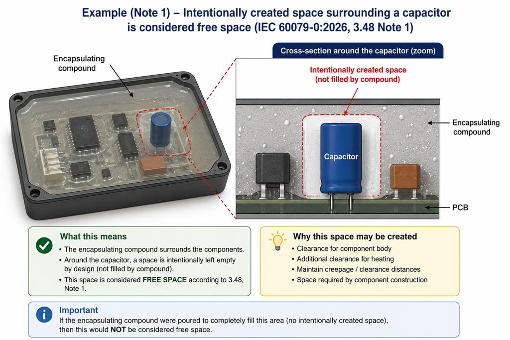 Note 2 means that a relay requires internal space for the contacts to move, and this empty space is not accidental, but is intentionally created for the device to function, so even if the relay is enclosed in an encapsulating compound, the empty volume inside the relay is considered Free Space. That is, external encapsulation does not necessarily make the internal space of the component disappear from the Free Space requirements.
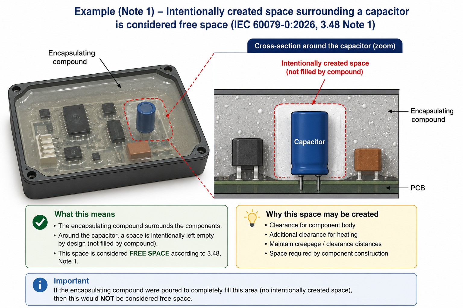
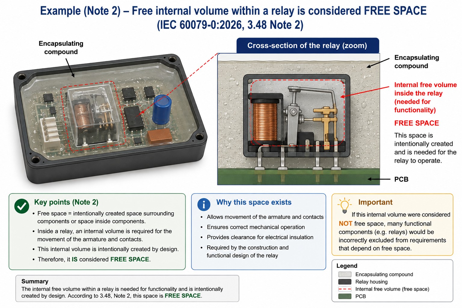
In the case of Note 3, let's assume that there is a small cavity inside a commercial IC that is not necessary for the IC's function, it was not created by the Ex equipment manufacturer and is simply a result of the manufacturing and packaging of the part. Therefore, the standard says that such a space is not considered a Free Space.
This distinction is very useful in practice because otherwise the manufacturer of an Ex Equipment would have to evaluate all the micro-voids and spaces inside commercial parts as Free Space.
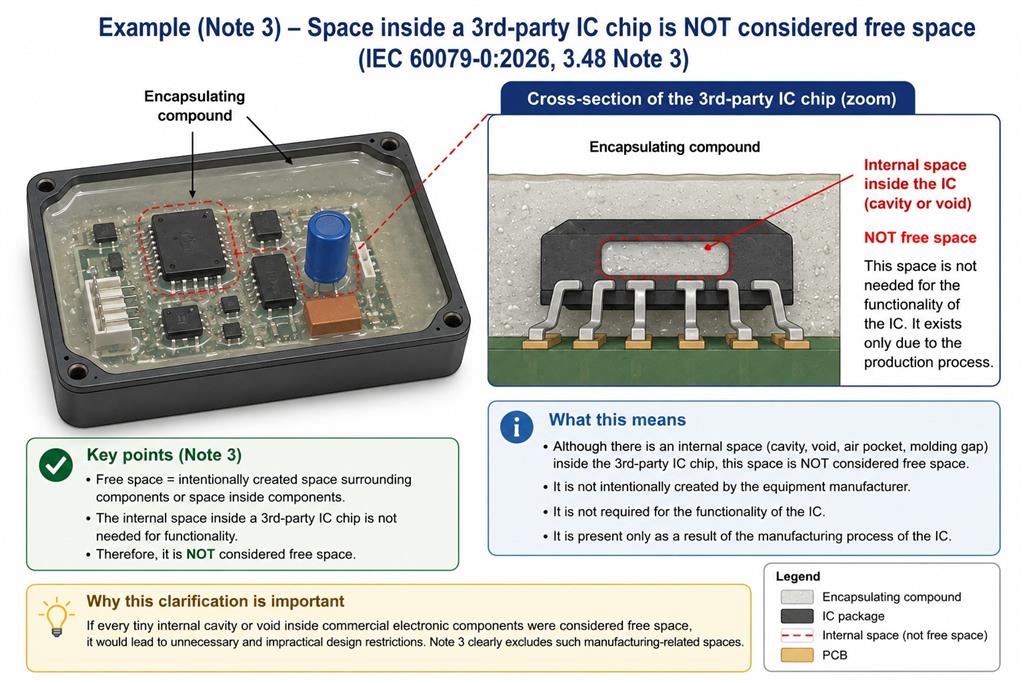 Therefore in the case of clause 3.48, the key question is no longer simply whether there is free space in or around the Component?
But why is this space there?
If the space is intentionally created for the function of the component or the design of the equipment, it is considered Free Space.
If the space is simply a consequence of the manufacturing process of a component and is not required for its function, then, as per the example in Note 3, it is not considered Free Space.
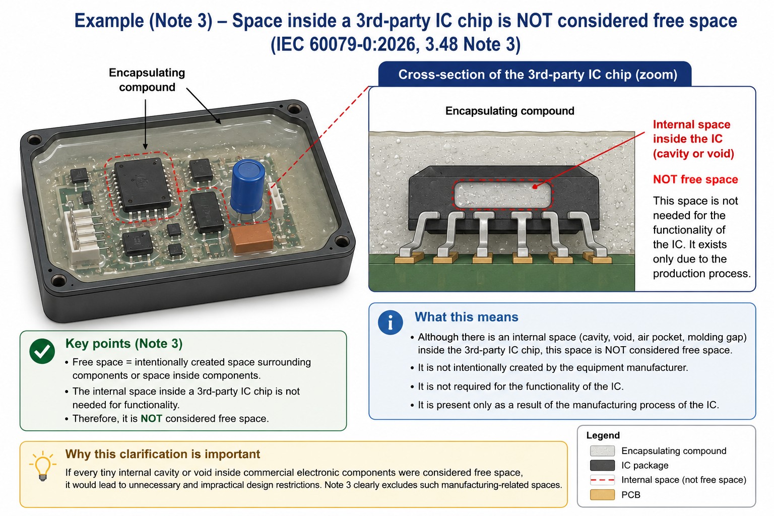
Impact on Design
These Notes can have a practical impact on Design Assessment, especially for equipment that has
-
encapsulation;
-
potting;
-
resin;
-
sealed components;
-
relays;
-
capacitors;
-
electronic assemblies
The designer must be able to determine which free space inside or around components is truly Free Space.
Important note: The Notes themselves do not create new design requirements, but rather clarify how to interpret the existing definition.
The actual requirement related to Free Space should therefore be derived from the relevant normative clauses and the relevant Type of Protection standard.
Impact on Technical File
If the design has encapsulation or associated internal spaces, the Technical File must clearly show the following:
-
The location of the components within the encapsulation;
-
The presence of intentional cavities;
-
Which cavities are essential to the function of the component;
-
Which cavities are purely due to the manufacturing process;
-
Their classification as Free Space or non-Free Space, where this affects compliance.
For example, in a drawing of an encapsulated PCB, if a relay is present, one cannot simply say that the complete PCB is encapsulated and ignore the internal volume of the relay, if the applicable requirement is dependent on free space.
Impact on Type Tests
These three Notes do not introduce new type tests per se, but they do change the applicability of the test to some components.
For example, if meeting a requirement or test requirement for some components in the relevant standard is a function of the amount of Free Space, Note 2 now clarifies that the functional space inside a relay cannot be excluded from the calculation/test simply because it is inside a component.
In contrast, Note 3 prevents non-functional cavities resulting from the manufacture of a commercial IC from being unnecessarily included in such an assessment.
Impact on Certification Body Assessment
The assessor should check whether there is free space within the encapsulated assembly.
If the answer is yes, the next step should be to determine its nature.
For example:
-
A capacitor within a designed cavity is considered free space.
-
A relay with internal space necessary for the movement of contacts is considered free space.
-
A microscopic/internal cavity within a third-party IC resulting from the manufacturing process is not considered free space.
The new Notes therefore provide the assessor with a clearer decision criterion and reduce the possibility of differences of interpretation between the manufacturer, laboratory and certification body.
24- Introduction of insulation coordination concepts in IEC 60079-0:2026
clause 3-Terms and definitions
sub-clause 3.55 insulation coordination
Type of the change: Minor and editorial
Rather than treating concepts such as overvoltage category and pollution degree as isolated definitions, IEC 60079-0 edition 8 organizes them together with several newly introduced concepts including isolated circuit, macro-environment, micro-environment and pollution in the framework of family of definitions concerning insulation coordination.
The significance-of-changes below table, identifies five terms as added, two definitions/notes as clarified, and two existing terms as relocated.
This new structure is important because it provides a common terminology for understanding how electrical insulation is influenced not only by voltage, but also by
-
electrical source;
-
transient overvoltages;
-
environmental conditions immediately surrounding the insulation;
-
isolation boundaries.
Clause |
Term |
Status in edition 8 |
|---|---|---|
3.55 |
Insulation coordination |
New term and definition added |
3.55.1 |
Isolated circuit |
New term and definition added |
3.55.2 |
Macro-environment |
New term and definition added |
3.55.3 |
Mains circuit |
Definition clarified |
3.55.4 |
Mains supply |
Note 2 clarified to address transient overvoltages |
3.55.5 |
Micro-environment |
New term and definition added |
3.55.6 |
Overvoltage category |
Existing term and definition relocated under insulation coordination |
3.55.7 |
Pollution |
New term and definition added |
3.55.8 |
Pollution degree |
Existing term and definition relocated under insulation coordination |
3.55 – Insulation coordination (New definition)
Edition 8 of IEC 60079-0, introduces insulation coordination as a new defined term which practically means that the insulation characteristics of electrical equipment should be considered in relation to the micro-environment in which the insulation operates and the stresses to which it can be subjected which originates from IEC 60050-442.
There was no corresponding definition of insulation coordination in IEC 60079-0 Edition 7.
The important point is that insulation performance should not be considered only from the viewpoint of the nominal or working voltage, rather the required insulation performance can also depend on factors such as:
Electrical stress → transient overvoltages → overvoltage category → environmental pollution → pollution degree → clearance and creepage distances
The purpose of adding such efinitiona, is to harmonize the terminology of IEC 60079-0 with the established insulation-coordination principles of IEC 60664-1.
3.55.1 – Isolated circuit (New definition)
solated circuit
|
|---|
It describes a circuit galvanically isolated from another circuit, such as a mains circuit, by an isolating element. The standard gives transformers, optical isolators and relays as typical examples.
Technical significance is that this definition helps establishing an important boundary in insulation coordination.
Mains → transformer → secondary electronic circuit
In the above arrangement, consider tat the primary circuit is exposed to the electrical conditions associated with the mains supply.
The secondary circuit, however, may be galvanically isolated from it.
Therefore, the insulation coordination assessment of every circuit within a piece of Ex Equipment does not necessarily have to assume that the circuit is directly exposed to mains transients.
Suppose an Ex control device contains:
230 V AC mains → isolation transformer → 24 V electronic circuit
In the above arrangement,the 24 V circuit is not simply another continuation of the mains circuit if adequate galvanic isolation exists.
Therefoe the new definition provides clear terminology for distinguishing these two circuit environments.
3.55.2 – Macro-environment (New definition)
macro-environment
|
|---|
It refers to the environment of the room or other location in which the equipment is installed or used. Edition 8 of IEC 60079-0 also directs the reader to IEC 60664-1 for additional information.
This point is important because the environment surrounding the equipment should not automatically be assumed to be identical to the environment immediately surrounding an insulating part inside the equipment.
For example, an Ex enclosure might be installed in a dusty industrial plant while a PCB located inside a sufficiently protected enclosure in the same dusty plant can experience substantially different local environmental conditions.
This distinction leads directly to micro-environment as the next new concept.
3.55.3 – Mains circuit (clarified definition)
mains circuit
|
Definition for mains circuit has been clarified, so that the edition 8 defines the mains circuit around two key characteristics:
-
it is intended to be directly connected to the mains supply; and
-
protection against transients on the electrical supply system has not yet been applied.
The accompanying note establishes an important boundary: the mains circuit extends up to components or devices providing transient protection, voltage limitation or isolation.
Mains input → SPD → power supply → isolated low-voltage electronics
in the above arrangement, the entire electrical system inside the equipment should not automatically be regarded as having the same exposure to mains transients.
The definition helps establishing where the mains circuit ends and can be particularly relevant when assessing insulation requirements on different sides of:
-
surge protective devices;
-
voltage limiting devices;
-
isolation transformers;
-
opto-isolators; or
-
equivalent isolation arrangements.
3.55.4 – Mains supply
mains supply
|
|---|
IEC 60079-0:2026 defines mains supply as the AC or DC power distribution system external to the equipment that supplies its operating power.
The definition makes clear that mains supply is not limited to a public utility. It can include private utilities and equivalent sources such as motor-driven generators and UPS systems.
Important clarification in IEC 60079-0 edition 8 for mains supply:
The Note 2 as having been clarified to address transients, therefore transient overvoltages are expected on mains supplies.
This statement is important for insulation coordination because insulation exposed directly to the mains cannot normally be evaluated as if only the steady-state operating voltage existed.
In simplified form: Mains supply ≠ only nominal voltage
Instead: Mains supply → operating voltage + expected transient overvoltages
This concept links 3.55.4 directly to the overvoltage category defined in 3.55.6.
3.55.5 – Micro-environment (New definition)
micro-environment
|
|---|
This is one of the most practically important additions in the whole 3.55 family.
IEC 60079-0 edition 8, defines micro-environment in terms of the ambient conditions that immediately influence the dimensioning of clearance and creepage distances.
Macro-environment vs Micro-environment
Industrial / hazardous location
│
│ MACRO-ENVIRONMENT
│
└── Ex enclosure
│
│
└── Internal PCB / terminals
│
│ MICRO-ENVIRONMENT
│
├── moisture
├── condensation
├── conductive contamination
└── local pollution
↓
Creepage / Clearance
This distinction prevents an overly simplistic assumption that the environmental conditions outside an enclosure necessarily exist unchanged at every insulating surface inside it.
However, being located inside an enclosure does not necessarily mean that an insulating part is exposed to a clean micro-environment. The actual internal conditions, including possible moisture, condensation or contamination, should be considered.
3.55.6 – Overvoltage category
numeral defining a transient overvoltage condition
|
|---|
This is not a new technical concept.
Edition 7 already contained overvoltage category in 3.63, defining categories I, II, III and IV with reference to IEC 60664-1.
Edition 8 of IEC 60079-0, relocates essentially the same concept to 3.55.6, explicitly placing it within the insulation-coordination family. IEC itself describes the change as: Term and definition for overvoltage category relocated to part of insulation coordination.
Why is the relocation useful?
Because overvoltage category determines the level of transient overvoltage exposure to be considered in insulation coordination.
Therefore, conceptually: Mains supply → transient exposure → overvoltage category → insulation requirement
The relocation makes this relationship much clearer than having overvoltage category as an isolated alphabetical definition.
3.55.7 – Pollution (New definition)
<of an electrical system> any condition of foreign matter, solid, liquid, or gaseous (ionized gases) that may affect dielectric strength or surface resistivity
|
|---|
Latest edition of IEC 60079-0, now explicitly defines pollution in relation to an electrical system which comprise foreign matter in solid, liquid or gaseous (ionized gases) form that can affect dielectric strength or surface resistivity.
important note: the pollution matters to insulation, because it particularly affects on creepage distance.
Contamination deposited on an insulating surface can increase its surface conductivity so that under suitable electrical and environmental conditions this can promote leakage currents (affecting dielectric strength) and surface tracking (affecting surface resistivity).
containations could include:
-
dust;
-
moisture;
-
conductive contamination;
-
condensation; and
-
industrial deposits.
an overview:
Pollution → change in surface electrical behaviour → influence on insulation performance
3.55.8 – Pollution degree
numeral characterizing the expected pollution of the micro-environment
|
|---|
This is not a new technical concept.
Edition 7 of IEC 60079-0 contained it as 3.65, defining pollution degrees 1, 2, 3 and 4 and referring to IEC 60664-1.
IEC 60079-0 edition 8 relocates the term to 3.55.8, immediately after the newly introduced definition of pollution.
This produces a much more logical relationship, rather than presenting pollution degree as an isolated definition.
Micro-environment → Pollution → Pollution degree
Practical significance
Pollution degree characterizes the expected pollution of the micro-environment, not simply the general external environment surrounding the equipment and
that distinction is important.
For example, the fact that equipment is installed in a dirty industrial area does not by itself mean that every PCB surface inside a suitably protected enclosure necessarily experiences exactly the same pollution conditions.
The assessment concerns the conditions actually influencing the insulation.
How do all the new definitions work together?
The most useful way of understanding the change is not to study the nine definitions separately, but to view them as a single insulation-coordination system.
the following diagram shows how electrical stresses and environment ultimately relate to insulation requirements.
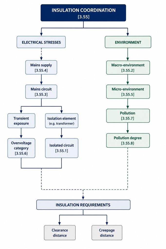
An isolated circuit can establish an electrical boundary between the mains circuit and downstream circuitry. For example, where a 230 V mains circuit supplies a 24 V circuit through an isolation transformer, the transformer provides galvanic separation. The downstream 24 V circuit can therefore be considered separately from the mains circuit when determining the insulation coordination conditions applicable to that circuit.
The diagram below, as a practical example, shows how the new definition of isolated circuit on the Electrical Stresses side works in a real device.
.jpg)
Does this change the design requirements for Ex Equipment?
The introduction of Clauses 3.55 to 3.55.8 does not, by itself, introduce a new general design requirement requiring the clearances and creepage distances of all Ex Equipment to be determined according to IEC 60664-1.
These subclauses are definitions in Clause 3. They establish and organize the terminology needed for insulation coordination, while the actual design requirements are specified in the applicable normative clauses of IEC 60079-0 or the relevant Type of Protection standard.
A useful example can be found in Clause 21.3 – Covers for luminaires of EPL Gc or Dc.
For certain energized parts that remain energized after operation of the disconnecting device, Clause 21.3 requires the clearances and creepage distances between phases (poles) and to earth to comply with IEC 60664-1, using Overvoltage Category II and Pollution Degree 3.
This provides a practical example of how the terminology grouped under the new Clause 3.55 can support an actual design requirement:
Overvoltage category [3.55.6] characterizes the transient overvoltage condition.
Pollution degree [3.55.8] characterizes the expected pollution of the micro-environment.
Micro-environment [3.55.5] refers to the ambient conditions that immediately influence the dimensioning of clearance and creepage distances.
Therefore, in the specific application covered by Clause 21.3
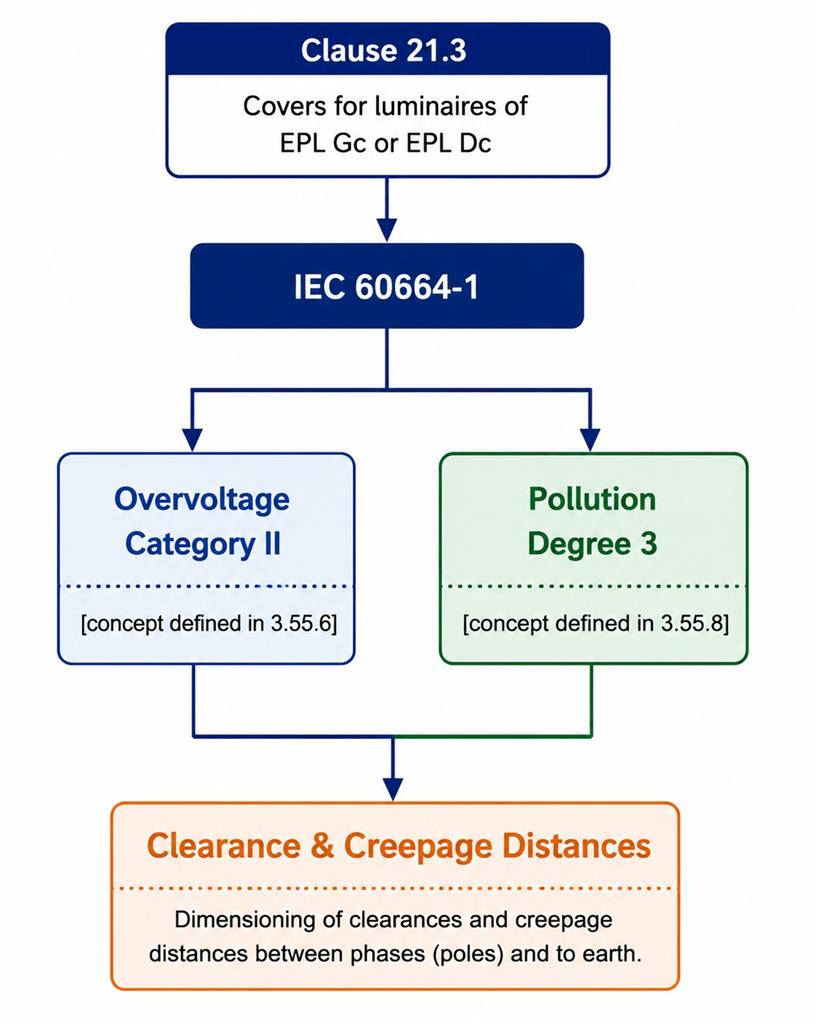
This example illustrates an important distinction:
Clause 3.55 provides the terminology and conceptual framework, while Clause 21.3 provides the actual design requirement and specifies the applicable insulation-coordination parameters.
Therefore, the addition and reorganization of the definitions under Clause 3.55 should not be interpreted as a universal new requirement to recalculate clearances and creepage distances for all Ex Equipment.
Instead, these definitions provide a clearer and more systematic vocabulary for applying insulation-coordination requirements where such requirements are invoked by the applicable normative clauses or Type of Protection standards.
This interpretation is also consistent with IEC's classification of all changes associated with Clauses 3.55 to 3.55.8 as minor and editorial changes, rather than extensions or major technical changes.
Impact on design
it afects low directly, but potentially useful for design interpretation, so that No redesign is automatically required merely, because 3.55 has been introduced.
However, designers now have clearer terminology for identifying:
-
where a mains circuit ends;
-
whether a downstream circuit is isolated,
-
what environmental conditions actually influence insulation, and
-
how overvoltage category and pollution degree fit into the insulation assessment.
This can make the justification of creepage and clearance distances more systematic and reliable where the applicable protection specific standard relies on these concepts.
Impact on certification and technical documentation
In cases where insulation coordination is required and relevant, e.g. different insulation assumptions are used for different parts of an equipment, the technical documentation can more clearly distinguish:
-
Electrical circuit → Transient protection/isolation boundary → Isolated circuit; and
-
Macro environment → Enclosure protection → Internal micro environment → Applicable pollution degree.
Impact on type testing
No new type test and assessment is created solely by Clauses 3.55 to 3.55.8. e.g. dielectric test or creepage or clearance checks.
obviously any applicable test or dimensional checks still has to originate from a normative requirement elsewhere in IEC 60079-0 or the applicable type of protection specific standard.
but the terminology can affect
-
how the applicable insulation requirements and
-
test conditions are interpreted.
25- relocation of an existing definition local temperature
clause 3-Terms and definitions
sub-clause 3.59 Local temperature
Type of the change: Minor and editorial
temperature of the air surrounding a component (but not the component surface temperature), taking into account the heat from the component and other nearby components, and where relevant, external sources of heating, under normal operating conditions |
This definition is not technically new.
In edition 7 of 60079-0, almost the same text was in footnote form under "Table 4 – Assessment of temperature classification / Component surface area ≥ 20 mm²".
In IEC 60079-0 edition 8, the definition has been moved to 3.59 and the corresponding table now refers to 3.59 with a footnote instead of repeating the definition.
What does local temperature mean?
The key point is that Local temperature is not the same as component surface temperature.
Suppose there are several electronic components located close together inside an Ex Equipment:
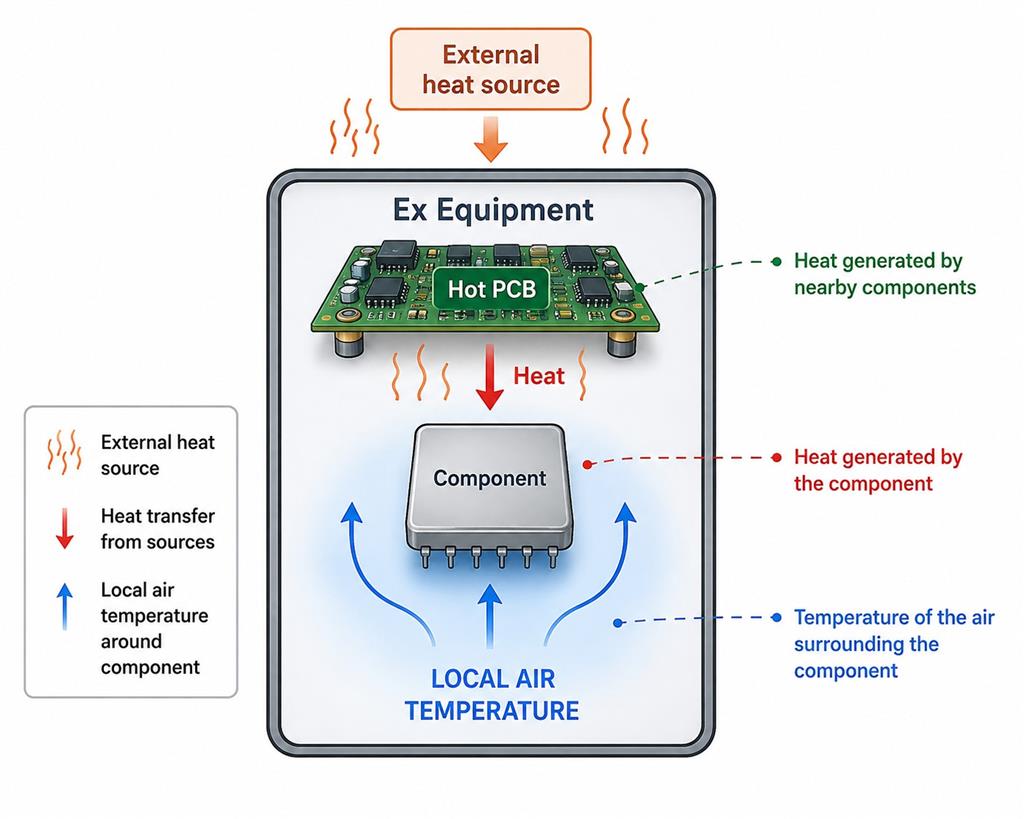
The air temperature immediately surrounding the component may be, for example, 60 °C, even if the general ambient temperature of the equipment is only 40 °C.
This can be due to a combination of these factors:
heat generated by the component itself + heat from nearby components + external heat sources
This actual air temperature around the component is the local temperature.
But if the surface of the component itself reaches, for example, 95 °C:
Local temperature = 60 °C
Component surface temperature = 95 °C
These two should not be confused with each other; the definition itself explicitly states the phrase but not the component surface temperature.
Why was the definition relocated?
This relocation was most likely done for clarity and uniform use of the term.
In Edition 7, the reader had to refer to the footnote to the table for a precise definition of Maximum local temperature in the temperature classification table. The definition was not in the general Terms and Definitions text.
In Edition 8, the IEC made it a separate defined term and the table says directly:
Maximum local temperatureᵃ → a See 3.59
In terms of the structure of the standard, this approach is much clearer: wherever the term local temperature is used in the standard, a single, formal definition is available in Clause 3.
Does this change the technical requirement?
No, The change does not introduce a new temperature concept or a new temperature limit; it gives an existing concept a formal and generally accessible definition in Clause 3.
Impact on Design
No direct new design requirement.
The designer already had to consider the local temperature surrounding the component when applying the relevant requirements.
However, Edition 8 makes it clearer that the thermal assessment of a component does not necessarily have to consider only the external ambient temperature of the equipment.
For example:
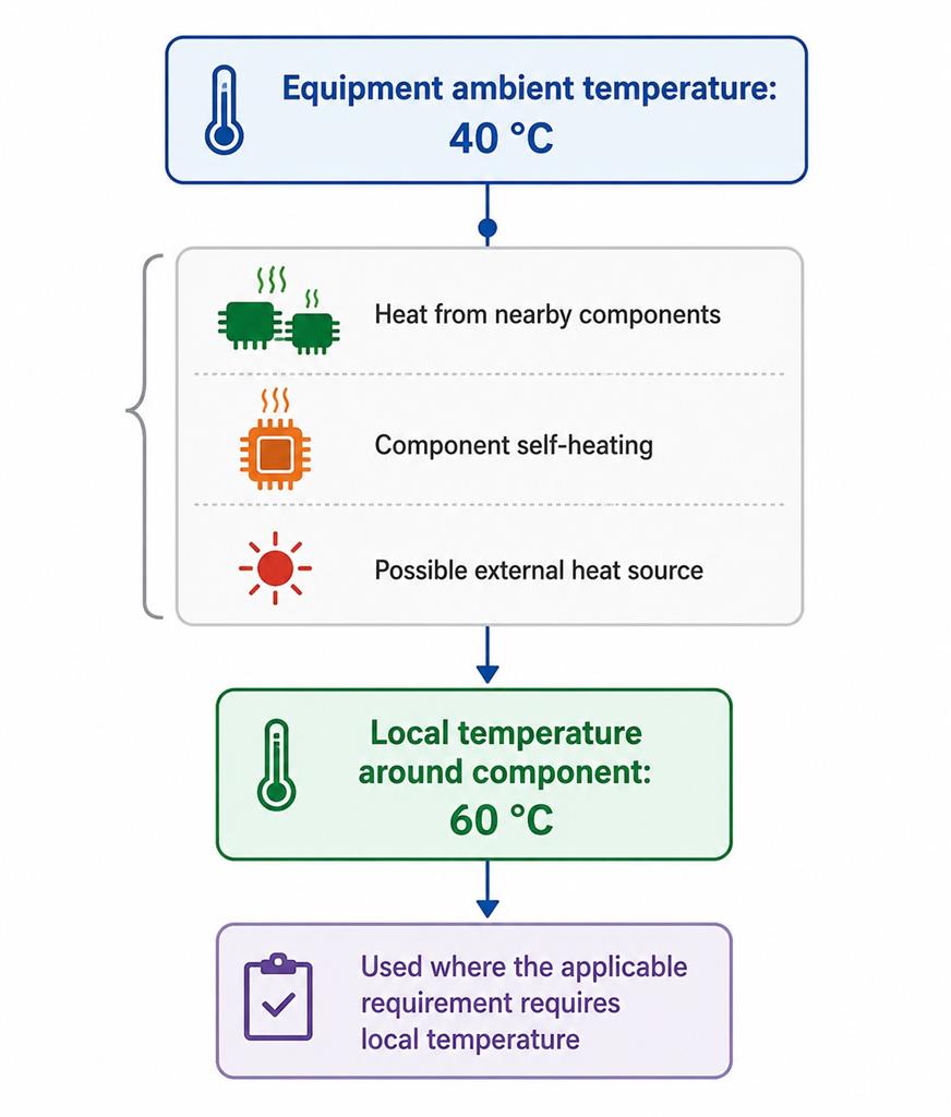
Therefore, Ta = 40 °C does not necessarily mean local temperature = 40 °C.
Impact on Certification and Testing
This change does not create a new type test per se, nor does it create a new requirement for temperature measurement from 3.59 itself.
Its importance lies more in the correct interpretation of test conditions and temperature assessment.
For example, Table 3 – Assessment of temperature classification in Edition 8 uses “Maximum local temperature” and now refers directly to Clause 3.59 for the definition of this term.
26- terminology harmonization: “Grounded” replaced by “Earthed” in the definition of propagating brush discharge
clause 3-Terms and definitions
sub-clause 3.67 propagating brush discharge
Type of the change: Minor and editorial
The replacement of “grounded” by “earthed” in clause 3.67 is purely an editorial terminology change. It aligns the definition with IEC 60079-0 terminology without changing the meaning of propagating brush discharge or introducing new design, testing, documentation or conformity assessment requirements.
Impact on Technical File, Type Testing and Conformity Assessment
Technical File
No new technical documentation is required. Where the term “grounded” is used in drawings, electrostatic risk assessments or specifications, manufacturers may update it to “earthed” for terminology consistency with Edition 8.
Type Testing
No new test or modification to existing electrostatic tests is introduced by this terminology change.
Conformity Assessment
No change to the conformity assessment process results from this amendment. Existing assessments concerning the prevention of propagating brush discharges remain technically applicable.
27- Broader definition of protective device from circuit interruption to Power supply interruption
clause 3-Terms and definitions
sub-clause 3.68 protective device
Type of the change: Minor and editorial
device provided to interrupt the supply of power in case a parameter exceeds a predetermined value
|
|---|
The phrase "interrupt an electric circuit", which was standard in the previous edition, has been removed and replaced with the phrase "interrupt the supply of power".
Why is this change important?
The old phrase interrupt an electric circuit could have given the impression that the protective device must necessarily open or interrupt an electrical circuit itself; for example, a circuit breaker, relay, or contactor.
The new phrase interrupt the supply of power focuses on the protective result: when a parameter exceeds a predetermined value, the protective device must cause the interruption of the relevant energy/power source.
This distinction is important, because the other definition does not describe the protective device solely in terms of the mechanical or electrical action of opening a circuit, but rather focuses on its function, i.e. removal/interruption of power supply.
For example, consider a thermal protection system:
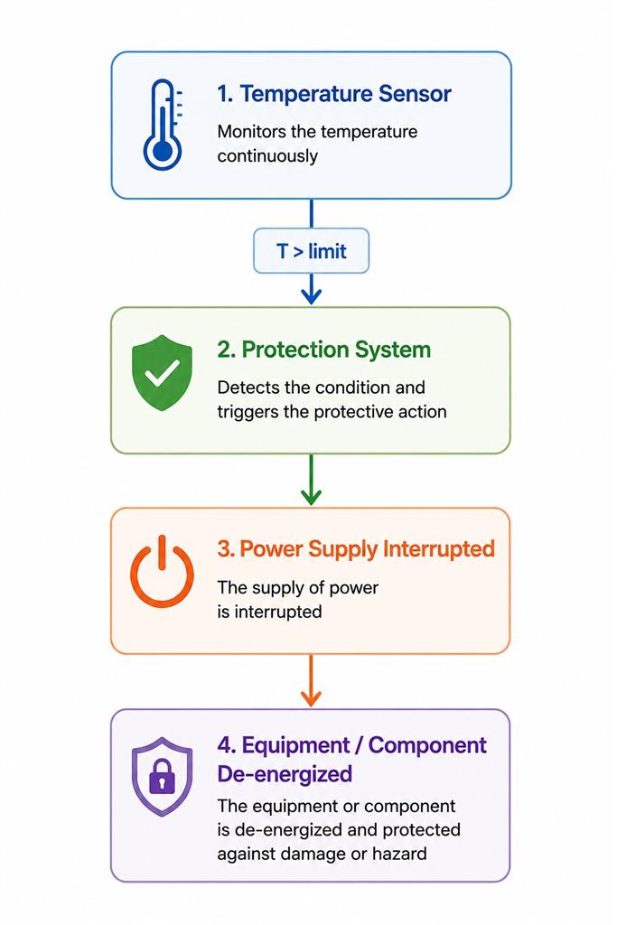
It is important here that the protective function ultimately interrupts the supply of power, and not that the definition of a protective device is limited to a device that directly opens or disconnects an electric circuit.
Note, however, that Note 1 has not changed fundamentally and the example parameters still include current, temperature, pressure, and flow.
The revised wording makes the definition more function-oriented.
instead of defining a protective device by the interruption of an electric circuit, IEC 60079-0 edition 8, defines it by its intended protective result: interruption of the supply of power when a monitored parameter exceeds a predetermined value.
This provides a broader and clearer description of the protective function without, by itself, establishing a new protection requirement.
Impact on Design, Technical File, Type Tests and Conformity Assessment
-
Design: This definition alone does not create a new design requirement. However, when a protective device is used to meet another requirement of the standard, the design must demonstrate that the protective function actually interrupts the supply of power under the specified conditions.
-
Technical File: No new document is required simply because of the change in 3.68. However, for important protective devices, it is better for the technical documentation to clearly state the monitored parameter, the predetermined trip value and the resulting interruption of power.
-
Type Testing: 3.68 OF iec 60079-0:2026, itself does not introduce any new tests. The testing of the performance of the protective device still follows from its normative clause, not from this definition.
-
Conformity Assessment: The certification or conformity assessment path does not change; but the new wording can help when examining protective functions to focus the assessment on whether the intended power interruption is actually achieved, not simply whether an electric circuit is opened in the narrow sense of the word.
28- New Definition of Equivalent Isotropically Radiated Power (EIRP)
clause 3-Terms and definitions
sub-clause 3.70.5 equivalent isotropically radiated power
Type of the change: Minor and editorial (technical clarification)
equivalent isotropically radiated power
|
|---|
EIRP = power supplied by a radio transmitter to an antenna × absolute gain of the antenna in a given direction.
This addition is particularly important because the revised definition of threshold power (3.70.6) now describes the RF power capable of causing ignition, while the former explanatory text in the edition 7 of IEC 60079-0, linking threshold power directly to EIRP has been removed.
The introduction of EIRP provides a clearer basis for assessing RF transmitters used in Ex equipment.
Where applicable, the ignition-risk assessment should consider not only the transmitter output power but also the antenna gain and the resulting effective radiated power.
Therefore, relevant RF characteristics may need to be documented in the Technical File and verified during conformity assessment.
The new definition does not, by itself, introduce a new type-test requirement and has no practical impact on equipment without RF transmitting sources.
Why is this change important?
In Edition 7, the concepts of transmitter output power, antenna gain and threshold power were partly explained in the definition of threshold power and antenna gain itself. In Edition 8, the conceptual structure is clearer:
Transmitter power + Antenna gain → EIRP → comparison with applicable RF ignition threshold
Therefore, when evaluating an Ex device with an RF transmitter, it is not enough to simply know the transmitter output power. If the antenna has gain, the effective radiated power in a given direction can be higher than the transmitter output power itself.
For example, conceptually: RF transmitter: 1 W, and antenna gain: 4 (absolute gain) → EIRP = 4 W
As a result, the ignition risk assessment must be based on the effective radiated condition, not just the 1 W entered for the transmitter.
Impact on Ex equipment design and Technical File
Area |
Practical impact |
|---|---|
Design |
Equipment containing RF transmitters may require consideration of both transmitter power and antenna gain. |
Technical File |
RF transmitter output power, antenna type/gain and the resulting EIRP should be identifiable where relevant to the ignition-risk assessment. |
Conformity assessment |
The assessor may need to verify that the RF energy potentially radiated by the equipment remains within the applicable ignition-safety limits rather than relying only on the transmitter's nominal output power. |
Impact on Type Testing
The addition of the EIRP definition alone does not require a new Type Test, but rather has a greater impact on RF ignition assessment and technical documentation.
That is, for equipment that does not have an RF transmitter at all, this change will have virtually no impact. However, for equipment such as: Wi-Fi / Bluetooth / RFID / cellular / telemetry / radio communication equipped Ex products This definition can directly affect the assessment of the Clause related to radio-frequency electromagnetic radiation.
29- Revised Definition of Threshold Power
Clause 3 – Terms and definitions
Sub-clause 3.70.6 – Threshold power (Pth)
Type of change: Technical clarification
RF power which, if exceeded, will cause ignition for continuous transmissions and for pulsed transmissions whose pulse duration exceeds the thermal initiation time. |
In Edition 8 of IEC 60079-0, the definition of threshold power (Pth) has been substantially revised.
In the previous edition, threshold power was defined in terms of the transmitter output power multiplied by the antenna gain. The associated notes also explained the relationship with antenna gain and considered the threshold power to be equal to the Effective Isotropic Radiated Power (EIRP).
In Edition 8, this approach has been replaced by a definition directly related to the RF power capable of causing ignition. Threshold power is now defined as the RF power above which ignition can occur for continuous transmissions, or for pulsed transmissions where the pulse duration exceeds the thermal initiation time.
Accordingly, the former explanatory notes concerning antenna gain and equivalence with EIRP have been removed.
The concept of EIRP is now separately defined in Clause 3.70.5, providing a clearer distinction between the radiated power characteristic of the transmitter/antenna system and the RF ignition threshold.
Practical impact:
-
The change clarifies that threshold power represents an ignition limit, rather than simply a calculated transmitter/antenna parameter.
-
For Ex Equipment incorporating RF transmitters, the applicable radiated RF power should therefore be assessed against the relevant ignition threshold requirements.
Technical file: Relevant RF transmitter characteristics, antenna parameters and the basis for demonstrating compliance with the applicable RF ignition limits should be clearly documented where RF transmission is present.
Type testing: The revised definition itself does not introduce a new type test; applicable RF ignition assessments and limits are determined by the relevant normative requirements.
Conformity assessment: During assessment of equipment containing RF transmitters, a clearer distinction should be made between the calculated radiated power, including EIRP where applicable, and the threshold power representing the ignition criterion.
30- Introduction of Relative Thermal Index (RTI)
Clause 3 – Terms and definitions
Sub-clauses 3.76, 3.76.1 and 3.76.2 – Relative Thermal Index (RTI)
Type of change: New definitions
3.76
|
Edition 8 introduces new definitions for Relative Thermal Index (RTI), establishing terminology for evaluating the long-term thermal performance of electrical insulating and polymeric materials.
RTI represents the temperature below which the critical performance of a material is not expected to be unacceptably degraded by thermochemical ageing during the reasonable service life of an electrical product, relative to a reference material having confirmed acceptable performance.
The standard identifies two RTI properties of particular relevance to IEC 60079-0:
-
RTI – mechanical impact (3.76.1): relates to retention of mechanical properties associated with impact resistance, toughness, elongation and flexibility.
-
RTI – mechanical strength (3.76.2): relates to retention of mechanical strength and structural integrity.
The RTI is determined in accordance with ANSI/UL 746B.
Practical impact:
The new definitions provide a standardized basis for considering the long-term thermal ageing of materials, particularly where continued mechanical performance of non-metallic materials is important for maintaining explosion protection.
Technical file: Material documentation may need to include the applicable RTI – mechanical impact and/or RTI – mechanical strength values, together with supporting material data or evidence established in accordance with ANSI/UL 746B, where required by the applicable clauses of IEC 60079-0.
important points:
-
RTI should not be presented merely as equivalent to the Temperature Index or the material's maximum service temperature.
-
RTI is specifically an indicator of the retention of a particular critical property following long-term thermal aging; for this reason, Edition 8 defines two separate indices including one for mechanical impact and one for mechanical strength.
Type testing: The introduction of these definitions does not by itself establish a new type test. Their testing and assessment implications depend on the normative clauses of Edition 8 that subsequently reference RTI.
Conformity assessment: Where RTI is invoked by the relevant material requirements, the certification assessment should verify that the specified material has appropriate RTI characteristics for its intended operating temperature and function.
31- Introduction of the definition of Schedule of Limitations
Clause 3 – Terms and definitions
Sub-clause 3.79 – Schedule of Limitations
Type of change: New definition
Schedule of Limitations
|
Edition 8 introduces a new definition for “Schedule of Limitations”, specifically in relation to Ex Components.
The term is defined as information necessary for the correct application of an Ex Component, which is provided on the corresponding Ex Component Certificate.
This addition formally establishes the meaning of a term that is important when an Ex Component is incorporated into complete Ex Equipment or another certified assembly.
The Schedule of Limitations identifies the conditions and restrictions that must be considered by the equipment manufacturer and certification body when applying the component.
Practical impact:
When an Ex Component is incorporated into Ex Equipment, its Schedule of Limitations must be reviewed to ensure that all applicable conditions and restrictions are properly addressed in the final equipment design and certification assessment.
Technical file:
-
The Ex Component Certificate and its applicable Schedule of Limitations should be included or referenced in the technical documentation.
-
Evidence demonstrating how each relevant limitation has been addressed should also be available.
Type testing:
-
The new definition itself does not introduce a new type test.
-
However, the Schedule of Limitations may specify additional evaluations or tests that must be performed when the component is incorporated into complete Ex Equipment.
Conformity assessment: ConformEx will verify that all applicable items in the Schedule of Limitations of any incorporated Ex Components, have been adequately addressed, before relying on the component certification as part of the equipment assessment.
32- Clarification of the Definition of “Special Fastener”
Clause 3 – Terms and definitions
Sub-clause 3.85 – Special fastener
Type of change: Editorial / Technical clarification
special fastener
|
In Edition 8, the definition of “special fastener” has been revised by removing the phrase “in accordance with IEC 60079-0.”
A special fastener is now defined more directly as a specific form of fastening device upon which a Type of Protection depends.
The revision
-
removes the unnecessary restriction of the definition to fastening devices specifically identified in IEC 60079-0 and
-
emphasizes the essential functional criterion in this form that:
-
a fastener is considered “special” when the integrity of a Type of Protection depends upon that fastening arrangement.
-
Practical impact:
The change does not fundamentally alter the concept or general requirements for special fasteners.
Manufacturers should continue to identify fasteners whose characteristics are essential to maintaining the applicable Type of Protection.
Technical file:
-
No specific new documentation requirement results from this definition change.
-
Relevant specifications and drawings should continue to clearly identify special fasteners where the Type of Protection depends on them.
Type testing: No new type test is introduced by this change.
Conformity assessment: The assessment should continue to verify compliance of applicable special fasteners with the relevant requirements, particularly Clause 9.2, to which the definition specifically refers.
33- New Definition of “Specific Conditions of Use”
Clause 3 – Terms and definitions
Sub-clause 3.86 – Specific Conditions of Use
Type of change: Minor and editorial
Specific Conditions of Useessential information for the installation, use, and maintenance of the Ex Equipment and is provided on an Ex Equipment certificate and the certificate number includes the suffix "X"See 3.89Note 1 to entry: These Specific Conditions of Use are in addition to the installation design, selection, installation of equipment, inspection, maintenance, repair, and overhaul requirements of the IEC 60079 series and the ISO/IEC 80079 series; and they do not repeat those requirements. |
A new standalone definition for “Specific Conditions of Use” has been introduced in Edition 8 of IEC 60079-0, so that Specific Conditions of Use:
-
are defined as essential information concerning the installation, use and maintenance of Ex Equipment,
-
is provided on the Ex Equipment certificate and
-
is identified by the suffix “X” in the certificate number.
The concept itself is not new, because In Edition 7, it was incorporated into the definition of the “X” suffix, which indicated that essential information for the installation, use and maintenance of the equipment was contained within the certificate.
Edition 8 therefore separates and formally defines the concept of Specific Conditions of Use as an independent term.
An important clarification is also included in the new definition:
-
Specific Conditions of Use are additional to, and
-
do not repeat, the normal requirements for installation design, equipment selection, installation, inspection, maintenance, repair and overhaul established by the IEC 60079 and ISO/IEC 80079 series.
Practical impact
No fundamentally new requirement for Ex Equipment is introduced by this definition.
Its main effect is to establish a clearer distinction between:
-
special conditions applicable to a particular certified product; and
-
the general installation, inspection and maintenance requirements already established by the relevant Ex standards.
For example, restrictions concerning a permitted installation orientation, protection from UV exposure, or particular measures against electrostatic charging can constitute Specific Conditions of Use when required for the certified equipment. Edition 8 continues to link such conditions with the “X” suffix.
Technical file
No new Technical File document is introduced solely because of Clause 3.86.
However, where Specific Conditions of Use are necessary, the technical documentation and instructions should contain sufficient information to support the conditions stated on the Ex Equipment certificate and enable them to be communicated correctly to the user.
Type testing
The introduction of the definition itself creates no new type test.
Specific Conditions of Use may, however, be resulted from limitations identified during design assessment or type testing.
Conformity assessment
No fundamentally new conformity-assessment procedure is introduced.
ConformEx determines whether:
-
limitations identified during assessment require Specific Conditions of Use; and,
-
where applicable, ensure that these are properly defined in the certificate and associated with the “X” suffix.
34- New Definition of “Supercapacitor”
Clause 3 – Terms and definitions
Sub-clause 3.87 – Supercapacitor / Electrochemical capacitor
Type of change: Minor and editorial
supercapacitor
|
Edition 8 introduces a new definition for “supercapacitor”, with “electrochemical capacitor” as an admitted term.
A supercapacitor is defined as a device that stores electrical energy using a double layer in an electrochemical cell.
The definition is adopted from IEC 60050-114:2014, 114-03-03.
The accompanying note specifically clarifies that an electrochemical capacitor is not to be confused with an electrolytic capacitor.
This new definition establishes consistent terminology for supercapacitors within IEC 60079-0, particularly where these energy-storage devices are addressed by the applicable requirements of the standard.
Practical impact
The addition of the definition does not by itself introduce a new technical requirement. It provides a clear and standardized meaning for supercapacitors/electrochemical capacitors, allowing requirements applicable to this type of energy-storage device to be interpreted consistently.
Technical file
No new documentation requirement results solely from the introduction of this definition.
Where a supercapacitor is incorporated into Ex Equipment, its relevant electrical and energy-storage characteristics should be documented as required by the applicable clauses of IEC 60079-0:2026.
Type testing
The new definition itself introduces no new type test.
Any testing requirements applicable to equipment incorporating supercapacitors arise from the relevant normative clauses rather than from Clause 3.87.
Conformity assessment
During conformity assessment, components falling within this definition, should be correctly identified as supercapacitors/electrochemical capacitors and assessed according to the applicable requirements of IEC 60079-0.